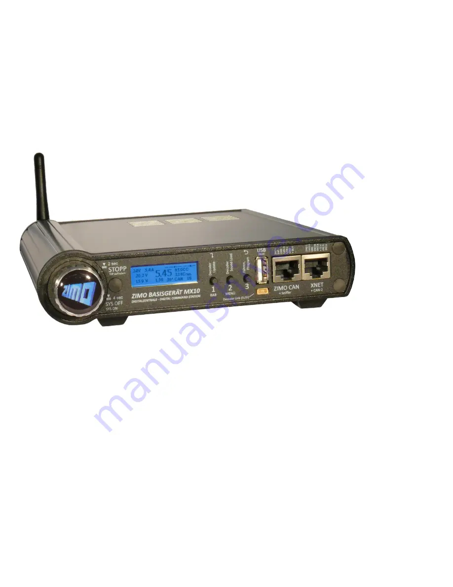
background image


CENTRAL COMMAND 
STATION MX10


ZIMO’s digital command station


This 

instruction manual

 contains elements which refer to features that are not yet fully imple-

mented.  
The final implementation may differ from the descriptions and  
display pictures.  


Chapter 


1.


Initial start-up of a ZIMO system

 ......................................................................... 4


2.


Power supply and technical data

 ........................................................................ 5
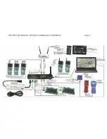
 

3.


Typical system arrangement

 ............................................................................... 6


4.


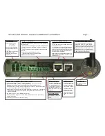
The “Connection and distribution board” MX10AVP

 ......................................... 12
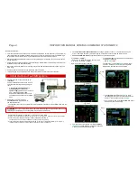
 

5.


Rail connections, programming track, AOS in/out

............................................. 15


6.


Track signal, Feedback, Database

 ................................................................... 17
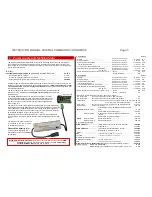
 

7.


MX10 update, data import and storage

 ............................................................. 18


8.


Usage and operating elements

 ......................................................................... 19


9.


“Roco Z21“ app and other apps on the MX10

 ................................................... 34


10.


Interlocking Program “ESTWGJ” on the MX10

 ............................................... 35


11.


USB connection to the  computer

 ................................................................... 37


Annex:  EMV audit report / TÜV Austria

 ..................................................................... 38


Annex:  Declaration of Conformity and Warranty

 ....................................................... 38


EDITIONS 

 2013 03 15 

2013 10 15 
2013 11 23 
2014 02 28 
2014 04 04 

   2014 04 05


2014 12 02 
2014 12 03 
2014 12 10 
2014 12 16 
2015 02 04 
2015 04 10 
2015 05 27 
2015 07 21 
2015 10 20


2015 12 07 
2016 02 11 
2016 03 14 
2016 04 05 

  SW 01.20.0001 - 2016 09 22 

2016 12 10 

SW 01.20.0150 - 2017 01 31 

2017 05 16 
2017 10.12 

SW 01.22.0001 - 2017 12 20 

2018 05 03 

SW 01.24.0001 - 2018 07 30 

2019 01 15 


INSTRUCTION MANUAL


Содержание MX10

Страница 1: ...se 17 7 MX10 update data import and storage 18 8 Usage and operating elements 19 9 Roco Z21 app and other apps on the MX10 34 10 Interlocking Program ESTWGJ on the MX10 35 11 USB connection to the com...

Страница 2: ...otection against erroneous activation Press and rotate shortly NO effect Rotating fast operating state VOLT AMP main settings screen YELLOW Pressing long 2 sec Broadcast Stop BCS and operating state S...

Страница 3: ...s for a 6 pole connection to ZIMO controllers and modules and or for an 8 pole connection to ZIMO stationary equipment modules StEin and compatible boosters as well as booster input and booster error...

Страница 4: ...tionally the most important connections have to be made with the existing material The controller one of the two sockets has to be connected to the MX10 socket ZIMO CAN via the CAN cable Connect the t...

Страница 5: ...in case of overcurrent adjustable in 0 1 sec steps 0 1 to 5 sec 0 2 s Tolerated overcurrent threshold surpassing adjustable in 0 5 A steps 0 to 4 A 0 A for a time of adjustable in 0 5 sec steps 1 to...

Страница 6: ...um setup of a ZIMO digital control is as follows The controllers MX32 and MX32FU tethered can be connected to the front and the rear CAN socket of the MX10 Due to the fact that the two CAN sockets are...

Страница 7: ...INSTRUCTION MANUAL CENTRAL COMMAND STATION MX10 Page 7...

Страница 8: ...anded wire with a 0 75 mm2 cross section correspond to about 0 01 Ohm 1 5 m stranded wire with a 2 5 mm2 cross section correspond to about 0 01 Ohm 2 5 m stranded wire with a 4 0 mm2 cross section cor...

Страница 9: ...resistance This can be guaranteed easily by certain lengths of wires and rails whereby the sum of both poles is effective 2 5 m stranded wire with a 0 75 mm2 cross section correspond to about 0 05 Oh...

Страница 10: ...used Each controller MX32 MX32FU MX31 is equipped with two equal 6 pole sockets which allows daisy chaining power supply and data from one controller to the next An alternative would be a 6 pole ring...

Страница 11: ...on the DiMAX immediately without takeover ROCO MultiMAUS connected to the MX10 The ROCO MultiMaus is connected via a normal 6 pole CAN cable to the XNET socket on the MX10 If MX32 FU are used addition...

Страница 12: ...sockets front and back this way 5 sock ets are available 4 of them on the MX10AVP This may be useful despite all devices having two CAN sockets for daisy chaining The MX10AVP s jumpers next to the soc...

Страница 13: ...ed MX32 forward all 8 poles of the CAN bus although they themselves only have 6 Fourth Example In case old and new generation devices shall work together two separate CAN buses are used This is the sa...

Страница 14: ...tionally to or instead of the CAN bus applications described above the connection and expan sion board MX10AVP is also used as connection to XpressNet devices Roco Lokm use or DiMAX Navigator radio re...

Страница 15: ...also when the actual overcurrent threshold is not yet reached Voltage and maximum current on the programming track in SERVICE MODE SERV PROG By default the voltage and current values on the programmi...

Страница 16: ...ime you probably need to activate BCS broadcast stop on track 1 an emergency stop button for this case has to be connected to in 7 and for its activation connected to the system s ground ground access...

Страница 17: ...sed in addition to RailCom as acknowledgement for the reception of DCC packets also of decoders which were produced before 2005 when RailCom did not yet exist but only loco number identification as fe...

Страница 18: ...id for the update of the MX32 FU The updating process The MX10 software update is done during operation If a flash drive with the usable files is connected all outputs on the MX10 are switched off All...

Страница 19: ...and the whole layout primary supply Voltage and current on output track 1 DC output S1 included Voltage and current on output track 2 DC output S2 included The power indicator for the DC in input pow...

Страница 20: ...needs Each of the values is displayed and has to be adjusted in dividually for track 1 and 2 Those lines are marked by 1 and 2 Additionally for addressing and programming procedures in service mode on...

Страница 21: ...threshold is allowed See de scription above OVC permitted current Spark suppression Range OFF LEV1 LEV2 Default LEV 2 Special circuits in the power amplifiers of the track outputs make sure that desp...

Страница 22: ...ON normal operation BCS OFF etc Example As soon as both track sections are turned on again after 2 sec it switches automatically to normal operation normal screen BLUE Press button 3 to not so normal...

Страница 23: ...fications OVF and TVF described in the following only occur in case the MX10 has a hard ware defect concerning the power supply circuits or if a power supply unit acts unexpectedly We recommend contac...

Страница 24: ...s speed slider the three buttons stay assigned the fixation is shown by the change of the cursor from to Press rotary knob LONG current speed step is fixed rotary knob is freely usable Mark another fu...

Страница 25: ...DR screen adjust the tagged value address with the rotary knob according to your wishes Press rotary knob program adjusted address into decoder Read out address As described above do not enter CV valu...

Страница 26: ...T1 and T2 all possible states of the tracks are set one after the other ON BSC OFF ON BCS OFF etc See chapter 8 3 Menu point VOLT AMPERE MAIN YELLOW Configuration of running voltages and maximum curr...

Страница 27: ...be Master or Booster Sniffer Input prepared Analog address i e virtual address can be called up from the controllers for analog vehicles which are controlled corresponding to NMRA with the stretched...

Страница 28: ...in the MX10 s file storage shall be used the available files are listed In contrast to the situation in which the updating procedure is started by inserting a flash drive to use a file directly from...

Страница 29: ...tions and response thresholds of the AOS inputs allocations to trigger BCS and OFF operating modes of the AOS outputs If the levels on the AOS inputs fluctuates between 120 and 140 this input is open...

Страница 30: ...object loco address received commands from the computer in the last 5 seconds HG CS both Display 3 DCC packet monitor function Shows in intervals of about 0 5 seconds what kind of pack ets were sent d...

Страница 31: ...e from database Press rotary knob screen colour changes to GREEN BaseCab screen Activision codes FG object is in the foreground on one controller HG object is in the LoR of at least one controller CS...

Страница 32: ...X10 Sound software decoder collection file and sound projects for decoders applicable via menu points ZIMO decoder SW Update and ZIMO decoder sound loading Menu points Data Clear Save Restore Clear GR...

Страница 33: ...directly from the flash drive or the MX10 s file memory Starting point normal screen BLUE EITHER from the flash drive Flash drive flash drive with decoder software collection file and or sound project...

Страница 34: ...has to be static Configuration on the MX10 see bottom of this page If this does not help the router has to be connected to the computer to determine the router s IP ad dress see chapter 10 Interlocki...

Страница 35: ...ter Necessary actions on the computer when connecting it directly via LAN cable Only use crosslink LAN cables The PC Laptop has to have a static IP address corresponding to the principles described be...

Страница 36: ...ion but can be interesting sometimes e g searching for bugs After Saving these settings in ESTWGJ the connection works As described here for ESTWGJ other interlocking programs can be connected with th...

Страница 37: ...e manager This COM port has to be changed to Com port 10 In case the COM interface was not automatically installed do it manually by following the described procedure Connect MX10 to USB and turn it o...

Страница 38: ...the date of purchase with proof of purchase from a ZIMO contractor The warranty covers the repair or replacement of defective parts ZIMO Elektronik GmbH reserves the right to proceed at its own discre...

Отзывы: