


INSTRUCTION MANUAL CENTRAL COMMAND STATION MX10 Page 23
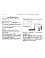
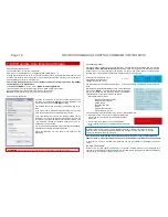
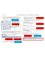
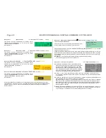
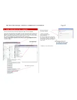
Overcurrent (short circuit) on track 1 or track 2
screen colour changes to
RED
,
or undervoltage on track 1 or track 2
STOPP & OFF screen.
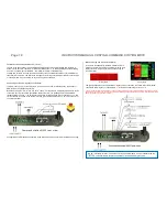
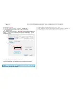
Starting point in this example: Normal screen
BLUE
Over-
current and undervoltage messages are shown on every
screen of the MX10 (e.g. LOCO, SERV PROG,...)
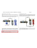
OVC = overcurrent
= current reached OVC threshold;
Turn-off because of overcurrent of the track on
which overcurrent (short circuit) was detected.
UNV = undervoltage
= power supply unit cannot provide the necessary
primary voltage to enable the necessary running
voltage. The primary voltage has to be at least 3 V
higher than the configured running voltage!
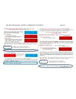
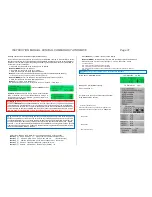
Those screens are the same as after starting broadcast stop (
“BCS”
or
“OFF”
) (except the text
“
OVC”
or
“UNV”
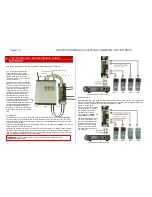
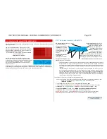
) from the MX10 or the controller. Therefore, also the procedure to re-start, etc. is the same:
Button 1
track-1
The states of track 1 and track 2 (independently
or with individual keys each) can be switched cyclical:
Button 2
track 2
OVC
(overcurrent) ->
ON
(normal operation)
BCS
(broadcast stop)
OFF
(turned off)
ON
...
e.g. turning on again with
button
1
(
):
switches automatically
(after 1 sec) to normal
screen
BLUE
.
... in case both track outputs are turned on again, the normal operation is reinstalled.
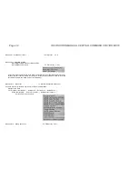
If it is not possible to start the normal operation via turning on both track outputs, then the error that
caused the OVC or UND is still not solved (principle of a FI). It is turned off again after the defined turn-
off time (VOLT & AMPERE detailed settings).
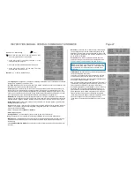
Described in the following: Reaction of the device its and handling
defects.
The notifications
“OVF”
and
“TVF”
described in the following only occur in case the MX10 has a hard-
ware defect concerning the power supply circuits or if a power supply unit acts unexpectedly.
We recommend contacting
ZIMO service
and/or sending it to
repair
.
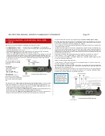
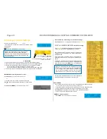
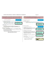
Wrongly detected overcurrent on track 1 / track 2
screen colour changes to
RED
,
STOPP & OFF screen
OVF
= “False” overcurrent
= current reached “false” OVC threshold
This notification (
“OVF”
) means that the track output was turned off because of “overcurrent” (actually
“OVC”
) although the value defined in “VOLT & AMPERE” was not reached, and also the power supply
unit does not provide too little voltage (this would be
“UNV”
). If this error occurs, the reason probably is
a defect in the current limiting circuit.
Voltage error on track 1 / track 2
screen colour changes to
RED
,
STOPP & OFF screen
TVF = Track voltage false (usually too high)
= the controlling voltage measurement on the
output detected a higher value.
This notification (
“TVF”
) means that the track output discharged a wrong voltage, usually higher than
defined in “VOLT & AMPERE”, and was therefore turned off automatically. This can lead back to a de-
fect or to an external voltage. The defect is potentially dangerous for the rolling stock, especially if it has
relatively low running voltages defined (and therefore the difference to the occurring overcurrent may be
relatively high).
These screens (
“OVF”
,
“TVF”
) and otherwise (except for the texts) are exactly the same as with
“BCS”
,
“OFF”
,
“OVC”
,
“UNV”.
Therefore, also the procedure to re-start, etc. is the same:
Button 1
track-1
The states of track 1 and track 2 (independently
or with individual keys each) can be switched cyclical:
Button 2
track 2
OVF
(overcurrent) ->
ON
(normal operation)
BCS
(broadcast stop)
OFF
(turned off)
ON
BCS
OFF
etc.
NOTE: OVP = Overcurrent on the programming track


