


INSTRUCTION MANUAL CENTRAL COMMAND STATION MX10 Page 9
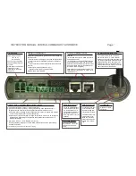
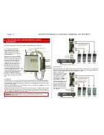
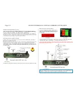
The devices communicate and synchronise via an
8
-
pole
CAN bus cable (type network cable); for all
devices only the CAN sockets on the
device’s back
may be used. Due to the fact that there is only
one such socket per MX10, you have to use a CAN bus distributor (
8
-pole
) for forwarding to a third
(...) device.
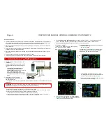
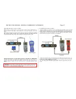
The track outputs of the central device and the booster device shall
not
be connected
directly
: each
track output should supply a layout area on its own. Nonetheless, the power circuits are connected
when a vehicle crosses the sectioning point.
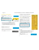
Therefore, a MINIMUM RESISTANCE of
0.05 Ohm
shall be guaranteed for the connecting wires (plus
rail resistance). This can be guaranteed easily by certain lengths of wires and rails (whereby the sum
of both poles is effective):
2.5 m stranded wire with a 0.75 mm
2
cross-section correspond to about 0.05 Ohm
10 m stranded wire with a 2.5 mm
2
cross-section correspond to about 0.05 Ohm
15 m stranded wire with a 4.0 mm
2
cross-section correspond to about 0.05 Ohm
25 m LGB-tracks (each of the two sides) correspond to about 0.05 Ohm
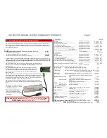
Attention: the MAXIMUM resistance shall be
0.1 Ohm
because otherwise the current equalization be-
tween the two outputs would no be possible due to the automatic voltage variation.
This leads to the recommendation:
Average cable length between output and track connection: 2 - 10 m
Connection cables > 10m: use at least a
4.0 mm
2
stranded wire!
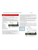
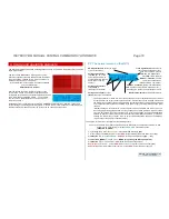
ATTENTION:
the 6POLTRIP (4-fold coupler for CAN bus wiring) should NOT be used to wire
boosters! For these cases use the MX10AVP-board.


