

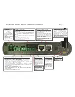

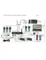


INSTRUCTION MANUAL CENTRAL COMMAND STATION MX10 Page 3
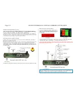
Track 2,
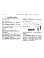
Primary supply
power supply unit with
20 - 35 V =
80 - 600 watt
You can only use galvani-
cally insulated power sup-
ply units!
MX10 powers up automat-
ically after connect-
ing/turning on the power
supply unit.
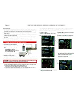
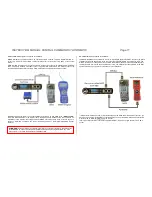
Outputs: track 1 | track DCs (DC out) S1, S2 | track 2
2-
pole socket “Schiene 1” (track 1) - usually main track
2-
pole socket “Schiene 2” (track 2) - usually programming track, additional circuit
“Digital current” (DCC, MM, in future possibly other track formats as mfx, sx)
Polarity N,P without meaning in simple applications, important on layouts with sections
or track sections (MX9, StEin, booster application)
Outputs track 1, track 2 according to voltage, current limits, etc. have to be configured
independently; depending on configuration and situation they use the same or a
different data signal.
3-
fold socket “DC out” “
-
S1, GROUND, S2
(S=track)
to supply stationary equipment modules StEin, track section modules, terminal loop
modules, and others.
All necessary plugs are included in the scope of supply.
Audio socket (line out)
For an amplified playback
of sounds which primarily
are reproduced by an in-
ternal speaker (from warn-
ing signals to sound pro-
jects; application is not yet
defined).
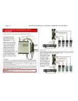
Sockets for ZIMO CAN and LAN
CAN bus
- for a 6-pole connection to ZIMO controllers
and modules; and/or
- for an 8-pole connection to ZIMO stationary
equipment modules “StEin” and compatible
boosters as well as booster input and booster-
error output (CAN and synchronization for ex-
ternal DCC-power amplifiers).
LAN interface as networkable alternative to a
USB-computer connection,or to a WiFi router
(tablet apps, etc.)
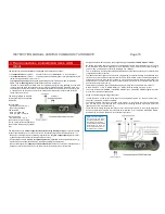
AOS inputs and LED outputs
8 logic-level inputs (react to ground and positive voltage, e.g.
track signal) for
- External buttons for emergency stop and emergency OFF,
- Track contacts for internal AOS (automatic operation se-
quences)
- Track contacts for external AOS (automatic operation se-
quences)
6 LED outputs (maximum load 25 mA) for
- Signals, various lights, controlled by AOS,
Supply pins 5V and GROUND.
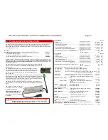
2.4 GHz antenna for Mi-Wi radio
To communicate with radio modules,
ZIMO uses “Mi-Wi”, a “mesh network”
based on components and the software of
the company Microchip, derived from the
ZigBee standard. The messages are for-
warded from nod to nod until they reach
their destination, even if there is no direct
radio connection at the moment.
It can be expanded to train radio.
USB (device) socket
Connection to the com-
puter via USB to use
with interlocking and
configuration software.
The transmission rate
corresponds to 1 M
Baud; the necessary
protocol can be down-
loaded from our web-
site.
LocoNet plug
Prepared for imple-
mentation.
Connection to power
Regulated DC connection
and ground 12 and 30
Volts.


