


INSTRUCTION MANUAL CENTRAL COMMAND STATION MX10 Page 13
MX32 MX32
MX31
MX9
Stationary equipment
module
“StEin“
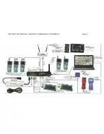
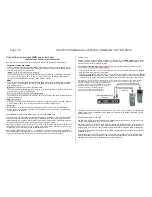
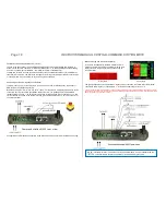
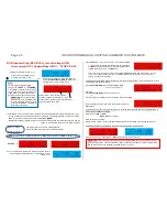
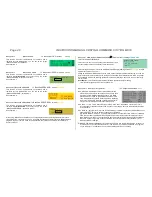
Third Example:
In this scenario, we only use new generation devices, controllers MX32 and stationary equipment
modules “StEin”; all work on CAN-1. The StEin modules (as well as booster MX10) need timing infor-
mation for the DCC track signal, additionally to the actual CAN data bus, wherefore 8-pole CAN cables
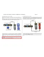
are needed. Those can be connected either
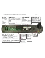
- from the back of the MX10 to the corresponding socket on the
MX10AVP
, or
- from the MX10AVP to the StEin modules themselves.
The jumpers (at the
best all 4 of them) have to be put on the position “Booster” (not “Sniffer”), so the
PCB can forward information and signals
.
Further devices and modules can be connected via the second parallely connected CAN sockets on the
devic
es themselves. For example MX32 and “StEin” mixed (MX32 forward all 8 poles of the CAN bus,
although they themselves only have 6).
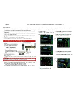
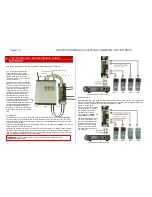
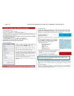
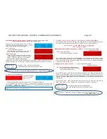
Fourth Example:
In case old and new generation devices shall work together, two separate CAN buses are used. This is
the same as using MX32 and MX31:
- old controllers (until MX31) and all accessory and track section modules (i.e. MX8, MX9 with valid ad-
dresses 801-863 or 901-963) on CAN-1
- new controllers (MX32, ...) as well as StEin modules on CAN-2.
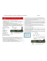
The sockets, to which
MX32 controllers and stationary equipment modules “StEin” are connected, have
to be set to “CAN-2”. Set the jumpers on the MX10AVP accordingly!
In the MX10 menu “Bus Monitor” configure “ZIMO (MX8/9)” for CAN-1, “ZIMO 2.xx(125)” for
CAN-2.
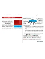
In case CAN power modules are used, they switch on after the MX10 finished starting up.
To compensate the ground in the system, connect MX8 and MX9 to the ground connector on the back
of the MX10 (DC out “M”).
Jumpers on “CAN-1”
All jumpers
on “Booster”
Jumpers to “CAN-2”
MX32
NOTE: as soon as one MX9 is connected, RailCom is deactivated on the whole layout. Also see
chapter “
Menu points DCC signal settings”


