


Page 30 INSTRUCTION MANUAL CENTRAL COMMAND STATION MX10
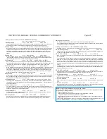
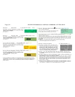
Menu point ObjectDB vehicles
object list by addresses
GREEN
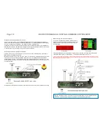
The centralised Object Database in the central command station usually contains automatically pro-
duced copies of all entries which are or were stored in the controllers (also if they were deleted from the
controllers in the meantime). This centralised database is the basis for the sending organisation of data
packets on the tracks as well as for transferring the GUI data between the input devices.
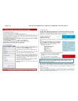
The menu point “ObjectDB vehicles” shows the contents of the centralised data base (registered loco
addresses including their current driving data and data communication statistics) which can also be
controlled there. Additionally, specific measures can be taken, especially deleting single addresses to
relieve the sending cycle, or stopping the trains.
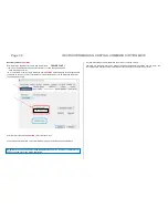
Calling up this menu point, the list of loco addresses with their (available) names, current speed step
and driving direction are presented (“basic display”).
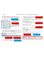
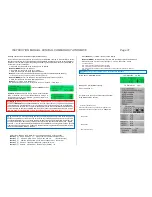
Rotary knob
Scrolling through the list of addresses, “
“ as the cursor shows the current position.
Button
1
(
)
Changes the information shown for each address
Basic display 0: Address Name MAN bit speed step direction arrows
*)
Button
1
(
)
Displ 1: Address “in” traction name (or number) activation code
**)
Button
1
(
)
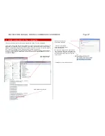
Displ 2: Address device info: on which device this address is active (also LoR)
Button
1
(
)
Displ 3: Address P F M „Fu“
x x
***)
Button
1
(
)
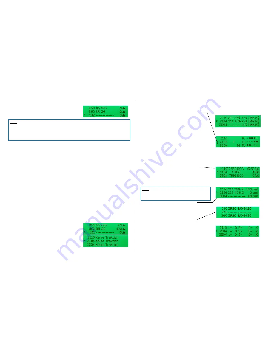
Displ 4: Address DCC packages / sec RailCom feedback / sec track format
***)
Button
1
(
)
Displ 5: Address feedabck (via RailCom) speed (km/h)
*****)
Button
1
(
)
Displ 6: Address manufacturer Decoder type (if ZIMO) ID
******)
Button
1
(
)
Displ 7: Debugscreen
*******)
Press
button
1
(
) LONG resume to basic display
Button 2 (MENU)
Submenu, inter alia, deletion from database (back from submenu with button 3)
Press rotary knob
to “BaseCab” screen (if by mistake, resume with button 3)
*)
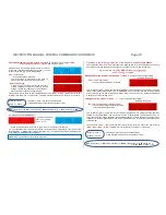
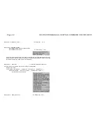
Basic display
Display 0: Name & driving data
Shows name (if available) and current driving data (i.e. MAN
bit, speed, direction) for the loco address in question.
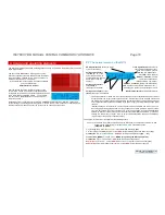
**)
Display 1: traction info and activation code
Those two do not have anything in common, they are com-
bined for reasons of space. Traction info shows, where appli-
cable, in which consist (name or number) or train the loco
address is integrated.
Activation codes in display 1:
FG object (loco address) is in the
foreground
on the controller
HG object (loco address) is in the
LoR
of at least one controller
CS this object (loco address) received commands from the
computer
in the last 5 seconds
HG CS both ….
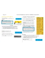
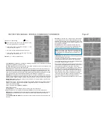
***)
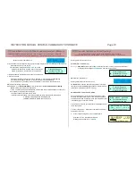
Display 3: DCC-packet monitor function
Shows in intervals of about 0.5 seconds, what kind of pack-
ets were sent during this period for this address. The “flick-
er
ing” frequency of a certain packet indicator (e.g. F or the
third
) represents the sending intensity of this data. If, for
example, the slider on the controller is moved, the “F” indi-
cator flickers every time, i.e. the DCC speed packet for this
second was sent at least twice per second.
Especially interesting for diagnose and analysis are of
course the addresses that are currently inactive or in the
background of an input device, and therefore rarely integrat-
ed in the “refreshing” cycle. Potentially appropriate actions
can be derived, like settings in “FUMZ” on the controller to
avoid unnecessary packet transmissions.
Types of packets and their indicators:
P
= programming commands (OP PROG);
F
= driving com-
mands (speed steps and direction);
M
= MAN bit; „
Fu
“
…
= the 5 function packets:
F0 .. F4
|
F5 .. F8
|
F9 .. F12
|
F13 .. F20
|
F21 .. F28.
****)
Display 4: DCC statistics & RailCom
This is where the number of sent DCC packets and received
RailCom feedback for the corresponding address is display:
In
the cursor’s line ”
“: Number/sec
In the other lines on the screen: cumulated number of pack-
ets / feedback since the last power on.
*****)
Display 5: RailCom notifications
This is where the content of the RailCom notifications is
shown, especially the speed feedback (km/h), but also other
information (compare: statistics of RailCom feedback in pre-
vious screen).
******)
Display 6: Decoder information
The most important information of the decoder of the corre-
sponding loco address, i.e. manufacturer (according to
“NMRA-ID” in CV #8), type (if ZIMO decoder or different reg-
istered manufacturer), ID (if available)
**)
Display 2: device info
*******)
Display 7: Debugscreen
NOTE: Driving operation is also possible without looking at the Object Database. In the ZIMO system,
almost any number of addresses can be managed at the same time; theoretically, the refresh cycle
holds up to 8000 loco addresses (compared to other manufacturers, who are usually limited to 64 or
128). If this possibility is used (to some extent), it may be useful to investigate, why reaction times, for
example, are getting longer, why refreshing packages are received infrequently, or which entries in the
database could be deleted - and actually deleting them.
NOTE: Those values only show, how many packets / feedback are
counted to a certain address and do not distinguish between differ-
ent types of packets (speed steps, function commands, etc.); the
latter is shown in the previous screen (packet monitor).


