


INSTRUCTION MANUAL CENTRAL COMMAND STATION MX10 Page 5
ATTENTION: Standard transformers
of all kinds (not even with rectifier) as well as
ZIMO
transformers
(although they were used for the MX1) and
old model railway
transformers
MUST NOT
be used with an MX10!
.
2.
Power supply and technical data
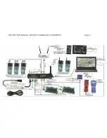
The central command station MX10 and all connected controlling devices (and the whole layout)
are supplied by an external power supply unit. This provides the so-
called “primary voltage”. As
power supply unit you can use a product from ZIMO or from another manufacturer, as long as it ful-
fills the basic requirements:
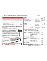
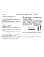
All power supply units provided by ZIMO correspond to these criteria. The current products can be
looked up in our product- and pricelist. The example shown here is
ZIMO’s standard power supply
unit with 30V and 8A
, this
power supply unit with 240W
is currently delivered with start sets, but
also available separately.
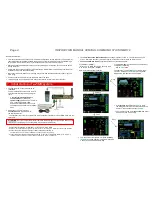
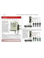
The track voltage on the MX10’s outputs is reduced by a DC converter inside the
MX10 to 10 - 24 V, depending on
voltage and current setting
(see chapter with
identical name).
The voltage difference between the MX10’s input voltage (i.e. output
voltage of the power supply unit) and track output voltage has to be 3V
or more because of the MX10’s internal use. Therefore, the track volt-
age has to be set to at least 3 V less than the voltage supplied by the
power supply unit.
The total current of the track outputs can be higher than the current supplied by
the power supply unit: the higher the total current (up to the double), the lower the
track voltages are configured compared to the voltage of the power supply unit.
This means that in case of a 240 W power supply unit, the total rail currents can
be calculated between 8 A (about 24 V) and 15 A (12 V).
Additionally to the track outputs there are other consumers (own consumption,
connected cabs, etc.), which limit the available power depending on their configu-
ration.
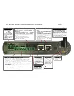
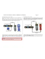
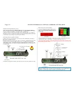
The output of the power supply unit
is connected to the “DC in” socket
on the MX10’s back side.
Observe the polarity (+/-)!
If it is connected wrongfully, the
MX10 does not start, but it CANNOT
be damaged.
Output
track 1
Default
- Voltage ............................................
(adjustable in 0.2 V steps) .....
10 to 24 V 16 V
- Start-up voltage .......................................
(adjustable in 1 A steps) ......
1 to 12 A 5 A
- Start-up time of the voltage ............................................
(adjustable in 1 sec steps) ......
1 to 60 sec 1 sec
-
overcurrent threshold ……………………...………………
(adjustable in 0.1 A steps) ......
1 to 12 A 5 A
- Turn-off time in case of overcurrent .....................
(adjustable in 0.1 sec steps) ......
0.1 to 5 sec 0.2 s.
- Tolerated overcurrent threshold surpassing ....
(adjustable in 0.5 A steps) ......
0 to 4 A 0 A
for a time of .................
(adjustable in 0.5 sec steps) ......
1 to 60 sec 0 sec
- Spark suppression
(selection between Off/Lev1/Lev2
)........ Level 1 ......................
8 A
OFF
Level 2 (sensitive) ......................
4 A
Output
track 2
Default
- Voltage ............................................
(adjustable in 0.2 V steps) .....
10 to 24 V 16 V
- Start-up voltage .......................................
(adjustable in 1 A steps) ......
1 to 8 A 3 A
- Start-up time of the voltage ............................................
(adjustable in 1 sec steps) ......
1 to 60 sec 1 sec
-
overcurrent threshold ……………………...………………
(adjustable in 0.1 A steps) ......
1 to 8 A 3 A
- Turn-off time in case of an overcurrent .....................
(adjustable in 0.1 sec steps) ......
0.1 to 5 sec 0.2 s.
- Tolerated overcurrent threshold surpassing ....
(adjustable in 0.5 A steps) ......
0 to 4 A 0 A
for a time of .................
(adjustable in 0.5 sec steps) ......
1 to 60 sec 0 sec
- Spark suppression
(selection between Off/Lev1/Lev2
)........ Level 1
8 A
OFF
Level 2 ... (sensitive) ....
4 A
DC outputs S1 and S2 (in the circuits for “track1” and “track 2”)
DC output 30 V
(Supply for devices connected via CAN bus cable) ...
4 A
DC output 12 V
(Supply for devices connected to XNET and LocoNet)...
1.5 A
LED outputs
(6 pins on 2x8-pole pin connectors)
- constant current at 15 mA .....
max. 25 mA
“out 5” and “out 6” are suitable for relay ...
100 mA
AOS inputs
(8 pins on 2x8-pole pin con.)
to ground or switching threshold
0 to 32 V
Audio output
(Jack socket 2.5 mm) ............................................
Line-out
RailCom
Detector track
1
measurable minimum amplitude of the RailCom sig-
nals...
4 mA
Sample rate (3-fold oversampling) ......................
750 kHz
Detector track 2
measurable minimum amplitude of the RailCom
signals...
4 mA
Sample rate (3 fold oversampling) ......................
750 kHz
ZACK
Detector track
1
Detection threshold ...............................
500 mA
Detector track 2
Detection threshold ...............................
500 mA
Communication via cable
ZIMO CAN bus 1 .....................
(ZIMO CAN sockets in the front and the back) ....
125 kBd
..............................
prepared for ............................
512 kBd
ZIMO CAN bus 2 .....................
(with special 8 pole cable: XNET socket) .......
125 kBd
........................
depending on the protocol up to .....
512 kBd
XNET ...................................................................................
62.5 kBd
XN2 ........................................
(2nd XNET or open DCC bus)
not yet in use
..
512 kBd
LocoNet .............................
at this moment the software is not prepared
.............................
16.6 kBd
USB device (client) interface.... ..............................................
1 Mbit/s
USB 2.0 host interface………
(for USB and future use)
.............
12 Mbit/s
LAN ………………………………..
(Ethernet, also to connect a WiFi router)
......
10 Mbit/s
Radio communication:
Mi-Wi network
(derivative of the ZigBee standard, 2.4 GHz) .......
~
20 kbit/s
Internal memory:
DRAM and SRAM (RAM)
64 MB
NAND flash (pictures, databases, interlocking systems, sound , etc.)
4 GB
DC
input:
external power supply unit
with galvanically insulated DC output
20-35 V
reasonable maximum voltage............................................................................
3 - 30 A
for minimum operation (about 3 A rail current).....................
.........................................
80 Watt
for operation with full power (up to 25 A total rail current)....................................
600 Watt
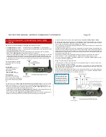
MX10, rear view


