Jupiter
S
UBSEA
D
ISPLAY
S
YSTEM
-
Q
UICK
S
TART
G
UIDE
Jupiter
Jupiter Subsea Display System Manual
Quick Start Guide
023-14-52-010 Issue 3
Page 2 of 2
PDF Date 13 June 2018
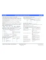
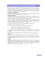
RS232 Serial Interface / Command Console Interface
The Subsea Display has an RS232 serial interface to allow configuration of various aspects of
the system functionality using the “Command Console Interface”. The system options
defined elsewhere within the system manual may be configured as required via the
Command Console Interface using a PC with an RS232 port and a communications program
such as “Windows Hyper Terminal”.
Normally the Jupiter Subsea Display system outputs the display reading over the RS232
serial interface whilst it is active.
The operational mode must be set for the system application, – see
“System Modes”
.
The system scale factors must be set to give the correct display for a given input, – see
“Calibration”
.
Note:
A Serial Interface Cable to connect to a standard PC 9 pin RS232 connector is supplied
with the Subsea Display System (Part No. 023-14-11-020). Connection to a USB port is
possible via a suitable USB to RS232 convertor. Contact Zetechtics, for further information.
RS232 Communication Parameters
Default
Data
Start
Stop
Parity Handshaking
19200
8
1
1
None
None
Note: Available baud rates 2400 to 115200 (see RS232 Console User Commands).
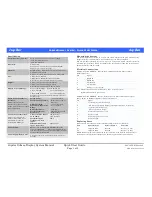
Option Links – (It is only necessary to open the system to configure
display brightness or strain gauge sensitivity!!!)
Links on Front Interface PCB 023-14-14-003 / 023-14-19-003 (nearest PCB to
display).
LK Option
Function
A
Light Sensor.
Swap Light Sensor Enabled / Disabled
State
B
Tare (Zero) switch.
Swap Zero Switch Enabled / Disabled
State
C
Scale switch, (no effect for strain gauge).
Swap Scale Switch
D
Not fitted to 2 Digit Quadrature Counter.
See Separate Table (below).
Display Brightness 1.
E
Display Brightness 2
Factory default link setting is A, B, C & E fitted / enabled.
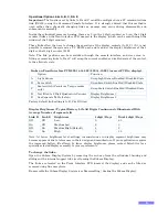
Display Brightness / Typical Battery Life All Digits Continuously Illuminated
With Average Number of segments lit
Link
D
Link
E
Brightness
4 digit / Days
Dual 4 digit /
Days
Off
Off
Low
9
4.5
On
Off
Medium Low
6
3
Off
On
Medium High (Default)
4
2
On
On
High
3
1.5
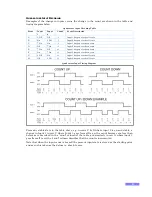
Strain Gauge Input Gain Setting – Links
The system has three gain settings, which should be selected based on the maximum
output (sensitivity) from the transducer.
Links on Strain gauge Interface PCB023-14-07-003 (2
nd
from Cylindrical
Housing End Cap)
Links
Transducer Sensitivity (mV/V)
A
(Default)
2
B
5
C
10
System Power Up / Operation
Ensure that the display face is exposed to daylight or artificial light.
Activate the Jupiter Subsea Display by fitting the RS232 Interface Cable or 5 way Power
Enable connector to Conn 1.
The Power – up Information Sequence is displayed.
The normal system display is shown with the display reset to zero.
The Subsea Display System is doing this, what does it mean?
Description
Cause
The display is illuminated
constantly
The light sensor is disabled. (Software or
Link A)
The display is only illuminated when
light is shone on the unit
The light sensor is enabled. (Software or
Link A)
The display is not illuminated at all
No connector in CONN 1
OR
There is insufficient light shining on the
unit and the light sensor is enabled
OR
The battery is completely flat
OR
A fuse has blown
The display shows ErHi
(Strain Gauge input)
The input value is above that set as
maximum or there is a sensor cabling /
connector fault.
The display shows ErLo
(Strain Gauge input)
The input value is below that set as
minimum or there is a sensor cabling /
connector fault.
The display is on continually except
for a brief flicker every six seconds
The light sensor is enabled (the unit
turns off the display briefly to test the
ambient light level).
The display is on continually except
for two brief periods every six
seconds
Low Battery


