39
P
OWER
B
ATTERY
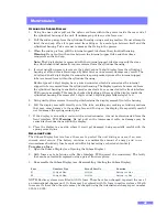
The battery installed is a high capacity Ni-MH ‘D-Cell’. If this fails it can be replaced with a
spare from Zetechtics Ltd, or in an emergency, an alkaline primary D-Cell such as a Duracell® or
similar, see Replacing the Battery.
S
YSTEM
C
HARGING
Note
: The display will flash twice every 6 seconds when the battery is low.
WARNING: Do not attempt to charge if Primary Cells are fitted
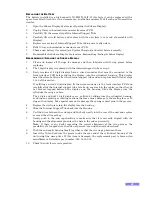
The system may be supplied with 2 types of charger:
WARNING:
Only use the New type of charger with systems labelled as compatible – contact
Zetechtics for details regarding compatibility.
New type International 100 to 240VAC charger: 023-14-02-005
1.
Disconnect the 5way Power Enable connector from the back of the system.
2.
Fit the correct international mains adapter supplied with the charger for the mains supply.
Attach the Charger (Part No. 023-14-02-005).
3.
The charger will charge until the battery is fully charged or for up to 10 hours and then
switch to trickle charging. If the battery is fully discharged a second charge cycle is
required. If the charge has run for around 10 hours before terminating, initiate a second
charge cycle by switching the charger off and back on again.
4.
To charge a fully discharged system takes approximately 16 hours.
5.
The discharge function may be used to fully discharge the system, but this should not be
required as the system uses NiMH batteries, that do not need a regular full discharge, like
NiCad batteries.
Older type UK 230VAC charger: 023-14-02-001
1.
Disconnect the 5way Power Enable connector from the back of the system.
2.
Attach the Charger (Part No. 023-14-02-001).
3.
Ensure that the charger is set to 600mA and 8 hours.
4.
To fully charge the system takes two 8-hour cycles. However if the battery still retains over
half its original charge, then it is reasonable to only execute one 8-hour cycle.
Checking the System Operation
1.
The batteries should be charged according to the instructions.
2.
The unit should be connected to a strain gauge sensor or counter input. The Power Enable
connector should be fitted.
3.
The current value is shown on the display.
Note
: If link A is fitted the display will only light up when there is some ambient light.
Remote - Display Zero Control
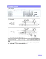
Items required for Remote - Display Zero, Reed Switch option.
1.
Cable: 999-11-07-003, 1 off.
2.
Reed Switch: 999-11-07-001, 1 off.


