background image


11


Method 1 – Calculating calibration scale factors 

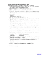
Calibrating a system with a known number of sensor targets and gearbox ratio: 

1.


Determine if 1 (Single input) or 2 (Quadrature) sensors will be used. 

2.


Determine the display precision required (number of decimal places). 

3.


Determine the number of sensor targets per rotation / unit length 

[A]

4.


Determine the gearbox ratio (eg 5 to 1 for 5 revolutions in to get 1 revolution out, or 1 to 1 

for no gearbox 

[B to C]

5.


Calculate the numerator and denominator as follows 
If single input  

D

  = 1 

If quadrature input  

= 4 

because there are 4 changes of state from the 2 sensors 

for each target 

Numerator 

  = 

C


Denominator 

  = 

A x D x B


6.


Correct for any decimal in denominator (multiply top and bottom by the same multiple of 

10) 

7.


Format Numerator  (add sign, decimal point and leading zeros as required)   and 

Denominator (add leading zeros as required). 

8.


Connect the system to a PC as described in the section on the 

Command Console 

Interface

 on page 27.  Enter the numerator and denominator using the commands: 

PNUM?????? 
PDEN???? 

9.


Check the calibration using the 

Calibration Check Procedure

 on page 15. 


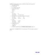
e.g.[1]

 The following is a simple example 

1.


QUADRATURE input 

2.


2 decimal place 

3.


A = 16

 targets per rotation 

4.


Gearbox None 

B = 1 
C = 1 

5.


D = 4


Numerator     = 1 
Denominator    = 16 x 4 x 1 = 64 

6.


There is no need to multiply both by a multiple of 10 to eliminate decimal in 

denominator 

7.


Format 
Numerator     = +01.00 
Denominator    = 0064 

8.


Program scale factors 
PNUM+01.00 
PDEN0064 

9.


Check the calibration using the 

Calibration Check Procedure

 on page 15. 

Содержание Jupiter

Страница 1: ...ONTROL SYSTEMS TM Tel 44 0 1653 602020 Fax 44 0 1653 691712 Email sales zetechtics com Website www zetechtics com Zetechtics Ltd Malton YO17 6TA England SUBSEA DISPLAY SYSTEM MANUAL INSTALLATION OPERA...

Страница 2: ...ftware supplied by us to you or you to us is confidential and supplied in confidence whether or not a contract comes into existence between us Zetechtics standard Confidentiality Agreement applies Jup...

Страница 3: ...te 5V Nominal or 10V Nominal 2kHz 250 seconds Power Supply Battery 1 D Cell Normally NiMH Rechargable Capacity 7000mAH May be fitted with Primary cell Duracell or equivalent for higher Capacity and or...

Страница 4: ...splay Brightness 1 E Display Brightness 2 Factory default link setting is A B C E fitted enabled Display Brightness Typical Battery Life All Digits Continuously Illuminated With Average Number of segm...

Страница 5: ...r System is highly complex and should only be operated maintained by suitable qualified experienced personnel In particular it is recommended that personnel undergo training by Zetechtics on all aspec...

Страница 6: ...isplay 8 Dual Input Quadrature Continuous Display 8 Dual Input Quadrature Bipolar Continuous Display 8 Dual Input Quadrature Bipolar Overflow Display 8 QUADRATURE INPUT DECODING 9 CALIBRATION PROCEDUR...

Страница 7: ...dure 27 RS232 DATA OUTPUT 28 RS232 Serial Data Format 28 DUAL DISPLAY RS232 SERIAL DATA FORMAT 28 RS232 CONSOLE USER COMMANDS 29 Command Summary General Use 29 Command Summary Quadrature Counter 30 Co...

Страница 8: ...3 SYSTEM SPECIFICATION 44 ZETECHTICS CONTACT INFORMATION 45 TECHNICAL SUPPORT 45 AGENTS 45...

Страница 9: ...4 Digit Display Can be used as either a 4 digit counter display or a 4 digit strain gauge input display An externally applied magnet can quickly and easily zero the display as well as changing the un...

Страница 10: ...the system will be mounted directly to the Remote Actuator as detailed in the General Assembly Drawing Doc No 023 14 16 001 which in turn should be mounted using the 2 off mounting holes on the front...

Страница 11: ...an output of the Subsea Display Reading to third party equipment such as a data multiplexer or data logger The system options defined elsewhere within this manual may be configured as required via th...

Страница 12: ...s displayed in Volts with 3 decimal places and is displayed with the prefix b as shown No Equivalent 5 Display RS232 baud rate The present setting of the baud rate is shown together with the prefix R...

Страница 13: ...ed With Average Number of segments lit Link D Link E Brightness 4 digit Days Dual 4 digit Days Off Off Low 9 4 5 On Off Medium Low 6 3 Off On Medium High Default 4 2 On On High 3 1 5 Note At lower bri...

Страница 14: ...prior to the previous change of state next time it is triggered For a graphical representation of this see the section on Quadrature Input Decoding This can be achieved in a number of ways such as A...

Страница 15: ...or quadrature input mode is being used That is the unscaled count value is not signed The un scaled count may rollover from 9999 to 0 or 99 to 0 for the 2 digit counter or vice versa in quadrature mo...

Страница 16: ...s 1 and 2 Unipolar mode continuous display with overflow indication disabled 0 1 2 3 9997 9998 9999 Dual Input Quadrature Bipolar Continuous Display Available with 2 or 4 digit display Setiqbc This co...

Страница 17: ...t 2 has gone to the on state G Off On 1 Input 1 has gone to the off state H Off Off 1 Input 2 has gone to the off state Quadrature Input Timing Diagram From any stable state in the table above e g in...

Страница 18: ...n of travel is positive or negative The position of the decimal point determines the displayed precision E g a numerator of 01 00 will give a displayed precision of 2 decimal places The numerator must...

Страница 19: ...or any decimal in denominator multiply top and bottom by the same multiple of 10 7 Format Numerator add sign decimal point and leading zeros as required and Denominator add leading zeros as required 8...

Страница 20: ...merator 2 Denominator 3 x 4 x 4 7 56 4 6 Multiply both by 10 to eliminate decimal in denominator Numerator 2 x 10 20 Denominator 56 4 x 10 564 7 Format Numerator 020 0 Denominator 0564 8 Program scale...

Страница 21: ...re the start and finish points are precisely marked and aligned both before and after to ensure the calibration procedure is accurate For example with a torque tool mark both the outer body and the dr...

Страница 22: ...Set scale factor to 1 5 Zero the display 6 Operate the tool for exactly 10 turns 7 Record a displayed value of 456 8 Write down numerator and denominator Numerator 10 Denominator 456 9 Format values N...

Страница 23: ...able number of turns for a torque tool but more turns will give a more accurate calibration particularly if the tool is intended to be used over many hundreds of turns 5 Record the displayed value the...

Страница 24: ...lways entered in the following format 6 characters including sign 4 digits left side padded with zeros and a decimal point Note The position of the Decimal point when the four digit numerator is enter...

Страница 25: ...user to precisely determine that the scaled count is exactly zero rather than a fractional value which displays as zero in the current display mode Rounded or Truncated both the 4 and 2 digit display...

Страница 26: ...degrees Anticlockwise Count 4 display shows 1 270 degrees Anticlockwise Count 3 display shows 0 180 degrees Anticlockwise Count 2 display shows 0 90 degrees Anticlockwise Count 1 display shows 0 0 deg...

Страница 27: ...inator results in digits to the right of the least significant digit being greater or equal to one half Example 1 If the input count is 1 and the denominator is 3 then the result of the division is 0...

Страница 28: ...sed on a 4 digit display A 2 digit display operates in the same way but with 2 digits displayed Overflows In some counting modes an Overflow display value is used This represents an imaginary number t...

Страница 29: ...9 3 0 1 0 1 999 9 999 9 2 0 0 0 1 999 9 999 9 1 0 0 0 0 999 9 0 0 0 0 0 0 0 0 0 0 0 1 0 0 0 0 0 0 0 0 2 0 0 0 1 0 0 0 1 3 0 1 0 1 0 1 0 1 4 0 1 0 1 0 1 0 1 5 0 1 0 2 0 1 0 2 6 0 2 0 2 0 2 0 2 Bipolar...

Страница 30: ...changes Note that it may be necessary to enable the Remote Reed Switch prior to use This is done within the RS232 Console Interface using the command enable232zero This command enables the RS232 DATA...

Страница 31: ...e system 1 Reset calibration to default factory set condition METHOD COMMAND reset 2 With the transducer connected to the Subsea Display System and no load applied on the transducer zero the displayed...

Страница 32: ...mand Console interface type pfs 8192 The value to enter for the dead band function may be obtained by operating the system that applies Torque for example and noting the Subsea Display reading above a...

Страница 33: ...when the Strain Gauge input Subsea Display System is in TVS mode The mode is shown under Analogue Operation in the Command Console interface The unit of measurement for the variable being measured ma...

Страница 34: ...ft Reed Switches Either switch will change the units of the top display showing strain gauge input Torque between Nm and lb ft Right Reed Switches Either switch will simultaneously Tare the top displa...

Страница 35: ...he RS232 Serial Data Output simple to decode 1 Connect the Subsea Display System to a PC serial port using the cable provided 5w micro to 9 way D part number 023 14 11 020 2 Run Windows Hyper Terminal...

Страница 36: ...to be entered in lower case RS232 DATA OUTPUT After the console display has timed out the RS232 output reverts to broadcasting the displayed value Note that if the light sensor is enabled the RS232 st...

Страница 37: ...e Disable Deep Sleep mode Requires User Password deepsleepenable Enable Deep Sleep mode Requires User Password disablelightsensor Disable the Light Sensor 2 Requires User Password dwelltime Input a dw...

Страница 38: ...ond Requires User Password pfnumpsxxxx Program the Flow Numerator to 1 Per Second Requires User Password pfnumph xxx x Program the Flow Numerator to 1 0 Per Hour Requires User Password pfnumphxxx x Pr...

Страница 39: ...analogue system on display 1 4 Requires User or Supervisor Password settrunc Rounding Off Truncated Requires User Password unipolar Count Linearly Unipolar Mode Requires User Password zero Zero the In...

Страница 40: ...ser Password User Password disablezero Not applicable User Password User Password User Password User Password User Password enableunscaled Not applicable User Password User Password User Password User...

Страница 41: ...anges the baud rate of the serial port to 57 600 bits per second No change occurs until there is a power cycle on the system or the powercycle command is issued baud115200 Changes the baud rate of the...

Страница 42: ...ables the RS232 DATA LOOP BACK ZERO function The RS232 data output from pin 1 5 way connector is fed back into the data input pin 2 and a comparison carried out If there is no difference between them...

Страница 43: ...he Flow Numerator to 1 0 per Minute pfnumpmxxx x Program the Flow Numerator to 1 0 per Minute pfnumps xxx x Program the Flow Numerator to 1 0 per Second pfnumpsxxx x Program the Flow Numerator to 1 0...

Страница 44: ...is disabled sensepower10v Sets the sensor power to 10V while light is detected or the light sensor is disabled sensepowerconst Sets the sensor power for a constant output regardless of the state of t...

Страница 45: ...t of the system setiqc SET Input to Quadrature Continuous This command is essentially a short cut to 1 of 5 of the most obvious configurations for the deployment of the system setlbft Set the display...

Страница 46: ...t TVS mode tare Tare the current value unipolar Sets the display value to Unipolar mode where decreasing the count though zero results in a large full scale 9999 on the four digit display or 99 on the...

Страница 47: ...round 10 hours before terminating initiate a second charge cycle by switching the charger off and back on again 4 To charge a fully discharged system takes approximately 16 hours 5 The discharge funct...

Страница 48: ...cal housing For removal of 4 digit or dual 4 digit displays follow steps 5 to 6 5 Using circlip pliers remove the circlip which retains the display assembly into the housing 6 Pull the display assembl...

Страница 49: ...section If re fitting a wired 4 digit display fit the wired connector to the front interface PCB and carefully slide the internal support tube to take up any slack in the cables so that they do not b...

Страница 50: ...Ring grease prior to re assembly Please use grease sparingly since too much grease can causealeak path Only apply a thin film to the connector so that the rubber turns from matt to a shiny wet appeara...

Страница 51: ...MUR 023 14 52 131 4 Digit Jupiter Subsea Display 023 14 52 132 4 Digit Jupiter Subsea Display NAMUR 023 14 52 141 Dual 4 Digit Jupiter Subsea Display 023 14 52 142 Dual 4 Digit Jupiter Subsea Display...

Страница 52: ...r reed switch contact closures and 2 or 3 wire proximity sensors including NAMUR type Strain Gauge Sensor Interface Strain Gauge Measurement Accuracy 1 0 of full scale From 10 to 100 of full scale Off...

Страница 53: ...dress mailto support zetechtics com Zetechtics email Technical Support is available 24 hours a day 7 days a week Between midnight and 6am urgent support requests should be made to the technical suppor...

Отзывы: