Jupiter
S
UBSEA
D
ISPLAY
S
YSTEM
-
Q
UICK
S
TART
G
UIDE
Jupiter
Jupiter Subsea Display System Manual
Quick Start Guide
023-14-52-010 Issue 3
Page 1 of 2
PDF Date 13 June 2018
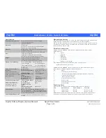
Specification
Operational Environment:
Fresh water or seawater to a depth of 3000m
-10 to +50°C Operational.
-20 to +65°C Storage
Electrical:
2 Connectors
Connector 1 – (5 way) – Power and data (RS232)
Connector 2 – (8 way) – Sensors
Material:
Main Housing – 316 stainless steel pressure housing
with removable end cap
Display – Acetal or 316 stainless steel, solid potted
Size:
2 Digit:- Ø50 x 199.5mm
4 Digit:- Ø50 x 230mm, Display 80 x 40mm
Dual 4 Digit:- Ø50 x 230mm Display 80 x 72mm
Weight:
2 Digit:-1.4kg (in air), 1.0kg (in water)4
4 Digit:-1.5kg (in air), 1.1kg (in water)
Dual 4 Digit:-1.6 kg (in air), 1.2kg (in water)
Display Type and Range:
Blue 7 segment LEDs – digits 14.2mm High
2 digit: -99 to 99
up to 1 decimal place
4 digit: -9999 to +9999
up to 3 decimal places
Leading zero suppression except immediately before
decimal point
Strain Gauge Transducer
Interface:
Suitable for 4 wire bridge
transducers such as pressure,
torque, load cell or other strain
gauge applications
Strain Gauge
Measurement Accuracy:
Offset Variation:
Transducer Sensitivity
Range:
Bridge Resistance:
System Calibration
Frequency:
± 1.0% of full scale
(From 10% to 100% of
full scale)
± 1.0% of full scale
2, 5 or 10 mV/V
>100 ohms
Minimum bi-annually
recommended
Counter Sensor Interface:
Suitable for reed switch
contact closures and 2 or 3
wire proximity sensors,
including NAMUR type
Counter Sensor Supply
up to 10mA:
Maximum Input
frequency on each
input:
Minimum dwell time
in any input state:
+5V Nominal or
+10V Nominal
2kHz
250µ seconds
Power Supply:
Battery – 1 D Cell Normally NiMH Rechargable
Capacity >7000mAH. May be fitted with Primary
cell – Duracell or equivalent for higher Capacity and /
or longer shelf / standby life.
Power Supply/Battery Life:
5 Days Average with continuous display, 5 Months
Standby.
Mounting the System
The system should be attached to a secure and stable structure with good visibility of the
display. Securing cylindrical body with a Jubilee® clip is an effective method.
The 4 Digit Subsea Display (not dual), may also be mounted within a Remote Actuator
Assembly, that provides a facility for switching the zero display, scaling and units functions.
Zetechtics Part No: 023-14-16-002.
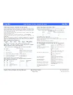
Electrical Connections
Conn 1
– Subconn MCBH5F – Power & Data, use RS232 Interface Cable or Power
Enable Connector.
Pin
Signal
1
RS232 Tx.
2
RS232 Rx.
3
0V / Battery.
4
0V / Circuitry.
5
Bve / fused at 1A.
Note: A) Power Enable Connector links pins 3 and 4 to enable system.
B) Charger Connects to pins 3 and 5.
Conn 2
– Subconn MCBH8F – Sensors / Transducers, see Sensor Connection diagram:
023-14-52-011 in Hardware Options section of this manual.
Pin
Signal
1
+ve Excitation (to Strain Gauge)
2
-ve Excitation (to Strain Gauge), (Also digital sensor 0V if required)
3
+ve Sense (to Strain Gauge)
4
-ve Sense (to Strain Gauge)
5
Sensor 1 5V or +10V
6
Sensor 1 Input
7
Sensor 2 5V or +10V
8
Sensor 2 Input
Replacing Fuses
Both fuses are to be found on the Rear Interface PCB (nearest the connectors).
Fuse
Nanofuse Type
Farnell Part No.
Function
F1
3A Quick Blow
992-2180
Bve Line
F2
3A Quick Blow
992-2180
Battery –ve Line
NOTE: Earlier systems were fitted with 1A fuses. These may be replaced with 3A fuses to
permit the use of international charger unit, Zetechtics part number: 023-14-02-005.


