9
Q
UADRATURE
I
NPUT
D
ECODING
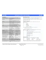
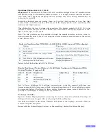
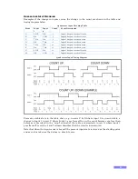
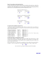
Examples of the change in inputs versus the change in the count are shown in the table and
timing diagram below.
Quadrature Input Decoding Table
Event
Input
1
Input
2
Count
Event Description
A
↓
Off
Off
-1
Input 1 has gone to the off state
B
On
↓
Off
-1
Input 2 has gone to the off state
C
↑
On
On
-1
Input 1 has gone to the on state
D
Off
↑
On
-1
Input 2 has gone to the on state
E
↑
On
Off
+1
Input 1 has gone to the on state
F
On
↑
On
+1
Input 2 has gone to the on state
G
↓
Off
On
+1
Input 1 has gone to the off state
H
Off
↓
Off
+1
Input 2 has gone to the off state
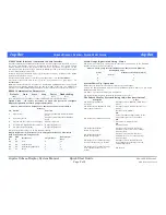
Quadrature Input Timing Diagram
From any stable state in the table above, e.g. in rows C & G where input 2 is on and stable, a
change in Input 1 in row C where Input 1 goes from off to on, the count becomes one less than
before as is described in the “count” column of the table, and similarly in row G where input 1
goes from off to on, the “count” column describes that the count is incremented.
Note that when the input count is ‘zeroed’ the present input state is stored as the starting point
and as such is taken as the datum i.e. absolute zero.

