3
G
ETTING
S
TARTED
C
ONNECTIONS
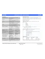
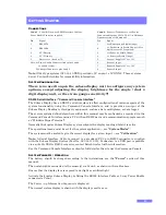
Conn 1
– Power & Data, use RS232 Interface Cable or
Power Enable Connector supplied.
Conn 2
– Sensors / Transducers, see Sensor
Connection diagram: 023-14-52-011 in Hardware
Options section of this manual.
Pin
Signal
Pin
Signal
1
RS232 Tx.
1
+ve Excitation (to Strain Gauge)
2
RS232 Rx.
2
-ve Excitation (to Strain Gauge), (Also
digital sensor 0V if required)
3
0V / Battery.
3
+ve Sense (to Strain Gauge)
4
0V / Circuitry.
4
-ve Sense (to Strain Gauge)
5
Bve / fused at 1A.
5
Sensor 1 5V or +10V
Note: A) Power Enable Connector links pins 3 and 4
to enable system.
B) Charger Connects to pins 3 and 5.
6
Sensor 1 Input
7
Sensor 2 5V or +10V
8
Sensor 2 Input
Note
: Older type systems (023-14-40-XXX) pr5V on pin 1 of CONN 2. These systems
do not. Contact Zetechtics for compatibility information.
S
YSTEM
C
ONFIGURATION
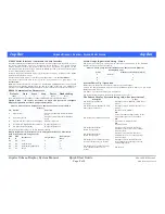
There is no need to open the subsea display unit to configure any system
options, except adjusting the display brightness for the single / dual 4
digit display unit, or the strain gauge sensitivity!!!
RS232 Serial Interface / “Command Console Interface”
The Subsea Display has an RS232 serial interface to allow configuration of various aspects of the
system functionality using the Command Console Interface, and to provide an output of the
Subsea Display Reading to third party equipment, such as a data multiplexer, or data logger.
The system options defined elsewhere within this manual may be configured as required via the
Command Console Interface using a PC with an RS232 port and a communications program such
as “Windows Hyper Terminal”.
Normally the Jupiter Subsea Display system outputs the display reading whilst it is active.
The operational mode must be set for the system application, – see
“System Modes”
.
The system must be scaled to give the correct display for a given input, – see
“Calibration”
.
Note:
A Serial Interface Cable to connect to a standard PC 9 pin RS232 connector is supplied
with the Subsea Display System (Part No. 023-14-11-020). Connection to a USB port is possible
via a suitable USB to RS232 converter, contact Zetechtics for further information.
See the Command Console Interface section for full details of how to use the Command Console.
S
YSTEM
P
OWER
U
P
/
O
PERATION
The battery should be charged according to the instructions, see the
“Power”
section of this
manual.
The unit should be connected to the sensor(s) via Conn 2, as shown in the table above.
Ensure that the display face is exposed to daylight or artificial light.
Activate the Jupiter Subsea Display by fitting the RS232 Interface Cable or 5 way Power Enable
connector to Conn 1.
The Power – up Information Sequence is displayed.
The normal system display is shown with the display reset to zero.


