41
R
EPLACING THE
B
ATTERY
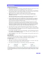
The battery installed is a high capacity Ni-MH ‘D-Cell’. If this fails it can be replaced with a
spare from Zetechtics Ltd, or in an emergency, an alkaline primary D-Cell such as a Duracell® or
similar.
1.
Open the Subsea Display System (see Opening the Subsea Display).
2.
Unplug 10way sub-miniature connector from rear PCB.
3.
Carefully lift the access strip of the Internal Support Tube.
4.
Carefully lift out old battery and replace with the new item (+ve to end of assembly with
Display).
5.
Replace access strip of Internal Support Tube taking care to align slots.
6.
Refit 10 way sub-miniature connector to rear PCB.
7.
Charge new battery if required (see System Charging) and retest before assembly.
8.
Re-assemble the Subsea Display System (see:
Reassembling / Sealing the Subsea Display
).
R
EASSEMBLING
/
S
EALING THE
S
UBSEA
D
ISPLAY
1.
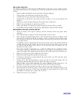
Clean and inspect all O-rings for damage and then lubricate with O-ring grease before
replacing.
2.
The 2 digit display is replaced with the internal support tube at step 5.
3.
Early versions of 4 digit displays have a wired connector that must be connected to the
front interface PCB before sliding the display into the cylindrical housing. This display
must therefore be fitted after the internal support tube and end cap has been fitted at steps
5 to 9 of this section.
If re-fitting a wired 4 digit display, fit the wired connector to the front interface PCB and
carefully slide the internal support tube to take up any slack in the cables, so that they do
not become trapped between the display and the housing. Slide the display into the
cylindrical housing as above.
The 4 digit and dual 4 digit displays are re-fitted by sliding into the cylindrical housing,
avoiding any rocking or twisting motions that may cause damage to the sealing face or O-
ring on the display. Take special care not to damage the sprung contact pins in the process.
4.
Replace the circlip to retain the display into the housing.
5.
Slide the Internal Support Tube back into the Housing.
6.
Coil the wires between the end cap and the body neatly into the rear of the unit and replace
or renew the silica gel bag.
7.
Gently push in the end cap checking to make sure that it is correctly aligned with the
housing and the alignment pin enters the hole in the end cap correctly.
Note
: If there is any doubt regarding the correct alignment of the two parts or the
possibility of a trapped wire, then do not proceed, open up the unit and recheck.
8.
Push the end cap & housing firmly together so that there is no gap between them.
9.
Insert the Nylon Cord into the groove inside the rear end of the cylindrical housing of the
unit using fine nose pliers. If this item is damaged, the replacement part is 2mm nylon
monofilament, Zetechtics part number: 023-14-00-005.
10.
Check the unit for correct operation.


