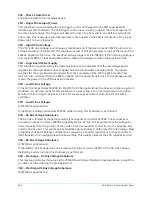
Table 201: Voltage thresholds
Supply voltage
range (Volts)
Shutdown
(volts)
Restart
(volts)
440-480
370
400
550-600
460
502
Supply Voltage
Range disabled
None
N/A
Starter – High Supply Line Voltage (Mod “A” Solid State Starter)
The voltage in any phase of the AC Power Line Voltage supplying the Solid State Starter has
increased to the high line voltage threshold for 20 continuous seconds. The chiller will automatically
restart when the voltage returns to the restart level. The thresholds are as follows:
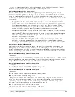
Table 202: Voltage thresholds
Supply voltage range (Volts)
Shutdown (Volts)
Restart (Volts)
380
415
414
400
436
435
415
454
453
440-480
524
523
550-600
655
654
Supply Voltage Range disabled
None
N/A
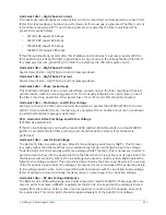
Proximity Probe – Low Supply Voltage
This message indicates the +24VDC power supply voltage to the Proximity Probe has decreased
to +19VDC. This is below the minimum level required for reliable operation. The chiller will
automatically restart when the voltage increases to greater than or equal to 19.7VDC.
Oil – Variable Speed Pump – Drive Contacts Open
The Oil Pump Variable Speed Drive has shut down the chiller by opening its status contacts
connected to the I/O Board TB3-70. The Drive initiates a shutdown anytime its internal protection
circuits will not permit the Drive to run. The contacts remain open until its internal protection
circuits are satisfied it is safe to operate. Some Drive initiated shutdowns require AC Power to be
cycled to clear the fault. The chiller will automatically restart when the contacts close.
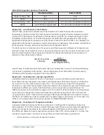
Mod “B” Solid State Starter cycling shutdown messages
LCSSS Initialization Failed
When AC Power is restored to the system after a power failure, an initialization process
occurs wherein the Control Center attempts to establish communications through the serial
communications link with the Liquid Cooled Solid State Starter. If communications are not
established within 10 consecutive attempts, a cycling shutdown is performed and this message is
displayed. The Control Center attempts to establish communications until successful.
LCSSS – Serial Communications
After communications have been successfully established in the Initialization process, the
Control Center initiates a data transmission to the Liquid Cooled Solid State Starter on the serial
communications link every 2 seconds. After these communications have been established, if the
Control Center does not receive a reply within 10 consecutive attempts, a cycling shutdown is
performed and this message is displayed. This same cycling shutdown is performed, along with the
199
YK-EP Style B Centrifugal Chiller
Содержание YK-EP
Страница 2: ...2 YK EP Style B Centrifugal Chiller...
Страница 6: ...6 YK EP Style B Centrifugal Chiller...
Страница 227: ...Figure 72 Sample printout of Status 227 YK EP Style B Centrifugal Chiller...
Страница 228: ...Figure 73 Sample printout of Status cont YK EP Style B Centrifugal Chiller 228...
Страница 229: ...Figure 74 Sample printout of Setpoints 229 YK EP Style B Centrifugal Chiller...
Страница 230: ...Figure 75 Sample printout of Setpoints cont YK EP Style B Centrifugal Chiller 230...
Страница 231: ...Figure 76 Sample printout of Schedule 231 YK EP Style B Centrifugal Chiller...
Страница 232: ...Figure 77 Sample printout of a Sales order YK EP Style B Centrifugal Chiller 232...
Страница 233: ...Figure 78 Sample printout of a Sales order cont 233 YK EP Style B Centrifugal Chiller...
Страница 234: ...Figure 79 Sample printout of History YK EP Style B Centrifugal Chiller 234...
Страница 235: ...Figure 80 Sample printout of History cont 235 YK EP Style B Centrifugal Chiller...
Страница 236: ...Figure 81 Sample printout of a security log report YK EP Style B Centrifugal Chiller 236...
Страница 260: ...Figure 87 Microboard 031 03630 007 Figure 88 Program card 031 03601 002 YK EP Style B Centrifugal Chiller 260...

