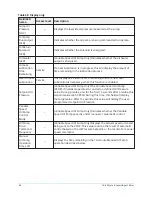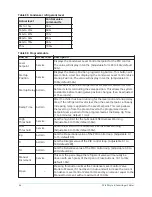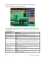
Table 85: Condenser refrigerant level
Actual level
Control valve
command %
0% to 15%
50%
16% to 31%
60%
32% to 47%
70%
48% to 63%
80%
64% to 79%
90%
79%
100%
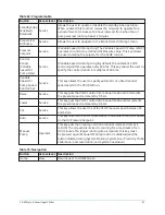
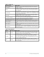
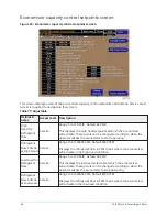
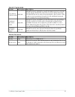
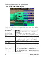
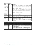
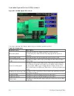
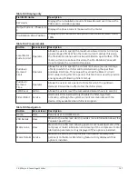
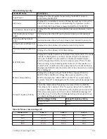
Table 86: Programmable
Button
Access level Description
Level
Setpoint
Service
Displays the Condenser Level Control Setpoint for the PID control.
The value will display in tenths. (Adjustable form 20 to 80%; default
50%).
Startup
Position
Service
Displays the Startup Position programming button. This button will
also contain a text box displaying the Condenser Level Control Valve
Startup Position. The value will display in tenths. (Adjustable 0 to
100%; default 50%).
Startup Delay Admin
The amount of time the refrigerant level valve PID waits after start
before it starts controlling the valve position. This allows the system
to stabilize before making valve position changes. (Can be adjusted
at 15 seconds).
Ramp Time
Admin
After the chiller has been running for the level control startup delay
time, if the refrigerant level is less than the Level Setpoint, a linearly
increasing ramp is applied to the Level Setpoint. This ramp allows
the level to go from the present level to the programmed Level
Setpoint over a period of time programmed as the Ramp Up Time.
(1 to 5 minutes; default 1 min).
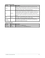
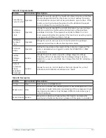
High
Threshold
Service
Sets the high limit for the Subcooler Effectiveness Warning
(Adjustable 0 to 100%; default 50%).
Low
Threshold
Service
Sets the low limit for the Subcooler Effectiveness Warning
(Adjustable 0 to 100%; default 50%).
Kp
Admin
Sets the Proportional value of the PID control loop. (Adjustable 0.1
to 15; default 0.5).
Ti
Admin
Sets the Integral value of the PID control loop. (Adjustable 0.1 to
500; default 200).
Td
Admin
Sets the Derivative value of the PID control loop. (Adjustable 0.0 to
200; default 0.0).
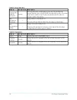
Manual
Increment
Service
This sets the percentage the refrigerant valve will manually be
driven with each press of the Open or Close buttons. (0.1 to 10%;
default 1.0%).
Open
–
Pressing this button will set the Condenser Level Control Valve
Mode to Manual, if it had been in Auto and will increase the current
Condenser Level Control Valve Command by an amount equal to the
Manual Increment, with a maximum of 100.0%.
YK-EP Style B Centrifugal Chiller
94
Содержание YK-EP
Страница 2: ...2 YK EP Style B Centrifugal Chiller...
Страница 6: ...6 YK EP Style B Centrifugal Chiller...
Страница 227: ...Figure 72 Sample printout of Status 227 YK EP Style B Centrifugal Chiller...
Страница 228: ...Figure 73 Sample printout of Status cont YK EP Style B Centrifugal Chiller 228...
Страница 229: ...Figure 74 Sample printout of Setpoints 229 YK EP Style B Centrifugal Chiller...
Страница 230: ...Figure 75 Sample printout of Setpoints cont YK EP Style B Centrifugal Chiller 230...
Страница 231: ...Figure 76 Sample printout of Schedule 231 YK EP Style B Centrifugal Chiller...
Страница 232: ...Figure 77 Sample printout of a Sales order YK EP Style B Centrifugal Chiller 232...
Страница 233: ...Figure 78 Sample printout of a Sales order cont 233 YK EP Style B Centrifugal Chiller...
Страница 234: ...Figure 79 Sample printout of History YK EP Style B Centrifugal Chiller 234...
Страница 235: ...Figure 80 Sample printout of History cont 235 YK EP Style B Centrifugal Chiller...
Страница 236: ...Figure 81 Sample printout of a security log report YK EP Style B Centrifugal Chiller 236...
Страница 260: ...Figure 87 Microboard 031 03630 007 Figure 88 Program card 031 03601 002 YK EP Style B Centrifugal Chiller 260...

