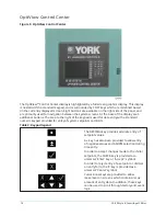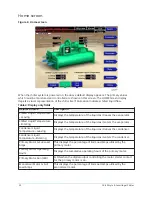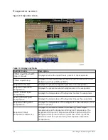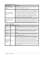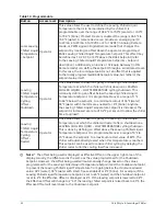
The Start/Stop control is operated via a soft Start/Stop key on the Home screen. Refer to
Interface conventions overview
The new graphical display on each control panel allows a wide variety of information to be
presented to the user. Each screen description in this document describes the graphical elements
on the screen and gives a short summary of the functions available. Each element on the screen will
then be categorized into three distinct groups: Display Only, Programmable, and Navigation. Below
is a short description of what types of information are included in these groups.
The programmable values and navigation commands are also subject to access level restrictions as
described below. For each of these elements, an indication is given to show the minimum access
level required to program the value or navigate to the subscreen.
Display only
Values in this group are read-only parameters of information about the chiller operation. This
type of information may be represented by a numerical value, a text string, or an LED image. For
numerical values, if the monitored parameter is above the normal operating range, the high limit
value will be displayed along with the ‘>’ symbol; if it is below the normal operating range, the low
limit value will be displayed along with the ‘<’ symbol. In some cases, the value may be rendered
invalid by other conditions and the display will use X’s to indicate this.
Programmable
Values in this group are available for change by the user. In order to program any setpoints
on the system, the user must first be logged in with the appropriate access level. Each of the
programmable values requires a specific access level which will be indicated beside the specified
value. All of the programmable controls in the system fall into one of the categories described
below:
Access level
In order to program any setpoints on the system, the user must first login with an appropriate
access level. When power is applied to the chiller, the system begins with an access level of VIEW.
This will allow the user to navigate to most screens and observe the values displayed there.
However, the user will not be allowed to change any values. To change any values, the user must
return to the HOME Screen (shown by default when power is applied to the system), and use the
LOGIN button or utilize the CHANGE SETPOINTS key described below. At this point, the user will be
prompted to enter a User ID and the corresponding password. By default, the User ID is zero (0). In
order to gain standard OPERATOR level access, the password would be entered as 9 6 7 5, using the
numeric keypad. OPERATOR access reverts to the VIEW level after 10 continuous minutes without a
keypress. If a custom User ID and password have been defined (refer to
), the user may
enter that User ID and the corresponding password value.
If the correct password is received, the user is authorized with the appropriate access level. If an
incorrect password is entered, the user is notified of the failure and prompted again. At this point
the user may retry the password entry, or cancel the login attempt.
Change setpoints
On screens containing setpoints programmable at the OPERATOR access level, a key with this
label will be visible if the present access level is VIEW. This key brings up the access level prompt
described above. It allows the user to login at a higher access level without returning to the HOME
Screen. After login, the user may then modify setpoints on that screen.
Setpoints
The Control Center uses the setpoint values to control the chiller and other devices connected to
the chiller system. Setpoints can fall into several categories. They could be numeric values (such
17
YK-EP Style B Centrifugal Chiller
Содержание YK-EP
Страница 2: ...2 YK EP Style B Centrifugal Chiller...
Страница 6: ...6 YK EP Style B Centrifugal Chiller...
Страница 227: ...Figure 72 Sample printout of Status 227 YK EP Style B Centrifugal Chiller...
Страница 228: ...Figure 73 Sample printout of Status cont YK EP Style B Centrifugal Chiller 228...
Страница 229: ...Figure 74 Sample printout of Setpoints 229 YK EP Style B Centrifugal Chiller...
Страница 230: ...Figure 75 Sample printout of Setpoints cont YK EP Style B Centrifugal Chiller 230...
Страница 231: ...Figure 76 Sample printout of Schedule 231 YK EP Style B Centrifugal Chiller...
Страница 232: ...Figure 77 Sample printout of a Sales order YK EP Style B Centrifugal Chiller 232...
Страница 233: ...Figure 78 Sample printout of a Sales order cont 233 YK EP Style B Centrifugal Chiller...
Страница 234: ...Figure 79 Sample printout of History YK EP Style B Centrifugal Chiller 234...
Страница 235: ...Figure 80 Sample printout of History cont 235 YK EP Style B Centrifugal Chiller...
Страница 236: ...Figure 81 Sample printout of a security log report YK EP Style B Centrifugal Chiller 236...
Страница 260: ...Figure 87 Microboard 031 03630 007 Figure 88 Program card 031 03601 002 YK EP Style B Centrifugal Chiller 260...

