background image

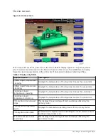
Economizer system screen

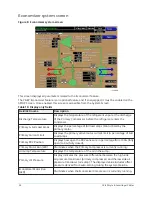
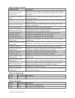
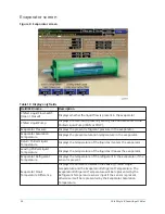
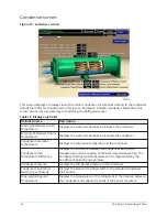
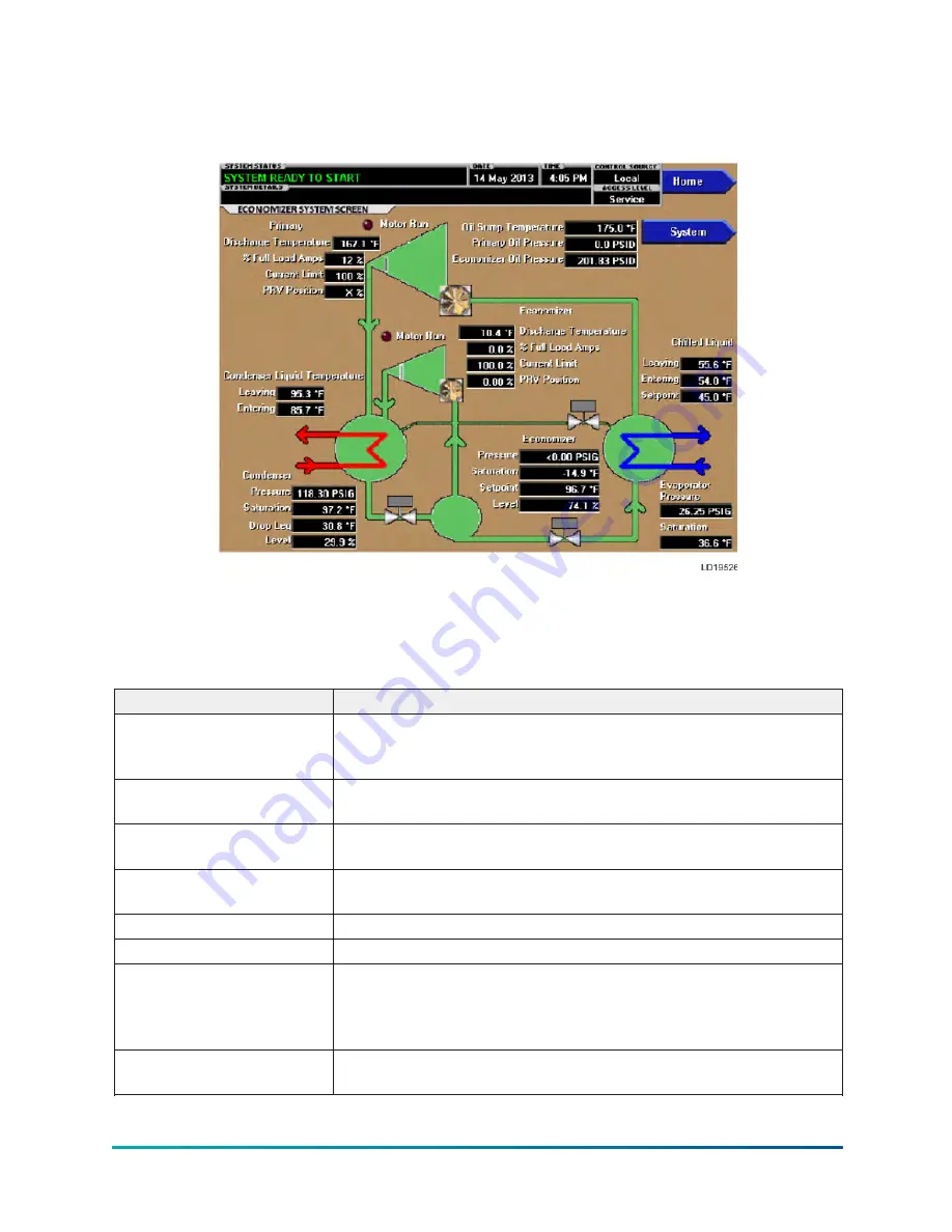
Figure 8: Economizer system screen

This screen displays all parameters related to the Economizer feature.
The YK-EP Economizer feature is an optional feature and if so equipped, it must be enabled on the

SETUP Screen. Once enabled, this screen is accessible from the System Screen.

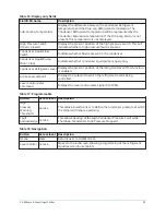
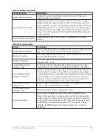
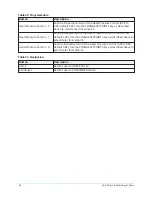
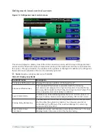
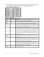
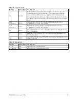
Table 10: Display only fields

Field/LED name

Description

Discharge Temperature

Displays the temperature of the refrigerant vapor at the discharge

of the Primary Compressor before the refrigerant enters the

condenser.

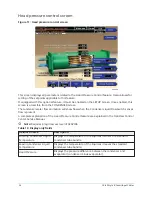
Primary % Full Load Amps

Displays the percentage of full load amps (FLA) utilized by the

primary motor.

Primary Current Limit

Displays the primary active motor current limit in percentage of Full

Load Amps.

Primary PRV Position

Displays how open the PRV vanes are in percentage from 100% (fully

open) to 0% (fully closed).

Primary Motor Run (LED)

Illuminates when the Primary Compressor is currently running.

Oil Sump Temperature

Displays the temperature of the oil in the sump.

Primary Oil Pressure

Display indicates the pressure differential between the high side

oil pressure transducer (primary compressor) and the low side oil

pressure transducer (oil sump). The displayed value includes offset

pressure derived from auto-zeroing during the system prelube.

Economizer Motor Run

(LED)

Illuminates when the Economizer Compressor is currently running.

YK-EP Style B Centrifugal Chiller

28

Содержание YK-EP

Страница 1: ...OM1 920 Supersedes 160 87 OM1 818 Operations and Maintenance Manual Issue Date 2020 09 15 YK EP Style B Centrifugal Chiller R 134a Cooling Only with OptiView Control Center Solid State Starter and Va...

Страница 2: ...2 YK EP Style B Centrifugal Chiller...

Страница 3: ...s bypass screen 57 Surge protection screen 60 Variable Geometry Diffuser screen 64 Variable Geometry Diffuser setpoints screen 66 Economizer compressor Variable Geometry Diffuser screen 69 Economizer...

Страница 4: ...9 Sales order screen 161 Economizer sales order screen 163 Operations screen 164 History screen 166 History details screen 168 Security log screen 169 Security log details screen 171 Custom view scree...

Страница 5: ...operating program 241 Program jumpers Program switches 243 Keypad interface 247 CM 2 board or Style A Solid State Starter interface 247 Configuration Setup 252 Downloading a program from a program car...

Страница 6: ...6 YK EP Style B Centrifugal Chiller...

Страница 7: ...cted that these individuals possess independent training that will enable them to perform their assigned tasks properly and safely It is essential that prior to performing any task on this equipment t...

Страница 8: ...ibility of rigging lifting and operating service personnel to verify the applicability of these documents to the equipment If there is any question regarding the applicability of these documents riggi...

Страница 9: ...NM5 Long Term Storage Periodic Checklist and Logs 50 20 CL5 Conditioned based maintenance Traditional chiller maintenance is based upon assumed and generalized conditions In lieu of the traditional ma...

Страница 10: ...quency in 60 Hz ECONOMIZER POWER SUPPLY 60 Hz 5 50 Hz DESIGN LEVEL SPECIAL FEATURES ECONOMIZER MOTOR CODE 60 Hz 50 Hz EF 5EC EG 5ED EH 5EE EJ 5EF EK 5EG EL 5EH EM 5EI EN 5EJ EP 5EK ER 5EL ES 5EM ET 5E...

Страница 11: ...perating status temperatures pressures and other information pertinent to operation of the chiller are automatically displayed and read on a graphic display Other displays can be observed by pressing...

Страница 12: ...ondensed refrigerant drains from the condenser into the liquid return line where the variable orifice meters the flow of liquid refrigerant to the cooler to complete the refrigerant circuit The major...

Страница 13: ...section diagram Table 1 Legend Callout Description A High pressure vapor B High pressure liquid refrigerant C Low pressure vapor D Low pressure liquid refrigerant E Intermediate pressure vapor F Inter...

Страница 14: ...sages There are certain screens displayed values programmable setpoints and manual control shown in this manual that are for Service Technician use only They are only displayed when logged in at SERVI...

Страница 15: ...Industrial chiller Exx Used on Microboard 031 02430 001 01 YKEP chiller xx controls revision level 00 01 etc y language package 0 equals English only 1 equals NEMA 2 equals CE 3 equals NEMA CE zz lang...

Страница 16: ...ith a standard numeric keypad provided for entry of system setpoints and limits Table 2 Keypad legend The DECIMAL key provides accurate entry of setpoint values A key has also been provided to allow e...

Страница 17: ...le controls in the system fall into one of the categories described below Access level In order to program any setpoints on the system the user must first login with an appropriate access level When p...

Страница 18: ...ice or oil pump speed Other keys in this category are used to initiate terminate processes such as calibrations or reports Free cursor On screens containing many setpoints a specific SOFT key may not...

Страница 19: ...able Speed Drive interface MV VSD Variable Speed Drive VSD screen VSD details screen Adaptive Capacity Control ACC details screen Surge map screen Table screen Harmonic filter details screen Motor lub...

Страница 20: ...Custom view screen Custom view setup screen Trend screen Trend setup screen Advanced trend setup screen Common slots screen YK EP Style B Centrifugal Chiller 20...

Страница 21: ...ser liquid temperature 8 0 133 5 F 13 3 56 3 C Evaporator refrigerant temperature optional 0 0 126 1 F 17 7 52 3 C Discharge temperature 31 8 226 3 F 0 1 107 9 C Oil temperature 31 8 226 3 F 0 1 107 9...

Страница 22: ...ature of the liquid as it enters the evaporator Condenser Liquid Temperature Leaving Displays the temperature of the liquid as it leaves the condenser Condenser Liquid Temperature Entering Displays th...

Страница 23: ...a SERVICE access level has been provided Only qualified service personnel utilize this access level This level provides advanced control over many of the chiller functions and allows calibration of ma...

Страница 24: ...e Shutdown is displayed on the System Status Line When the Vane Motor Switch VMS closes indicating the vanes have fully closed or 3 5 minutes have elapsed whichever occurs first the Run signal is remo...

Страница 25: ...m the Adaptive Capacity Control and Harmonic Filter information is controlled under this screen Setpoints This screen provides a single location to program the most common system setpoints It is also...

Страница 26: ...lays the temperature of the liquid as it enters the evaporator Chilled Liquid Temperature Setpoint Displays the active temperature setpoint to which the chiller is controlling the evaporator liquid Th...

Страница 27: ...ucer output of oil filter and the low side oil pressure transducer compressor housing The displayed value includes offset pressure derived from auto zeroing during the System Prelube If either of the...

Страница 28: ...zed by the primary motor Primary Current Limit Displays the primary active motor current limit in percentage of Full Load Amps Primary PRV Position Displays how open the PRV vanes are in percentage fr...

Страница 29: ...bundle Entering Condenser Liquid Temperature Displays the temperature of the liquid as it enters the condenser Condenser Pressure Displays the pressure of the refrigerant within the condenser Condens...

Страница 30: ...led Liquid Temperature Displays the temperature of the liquid as it enters the evaporator Leaving Chilled Liquid Temperature Displays the temperature of the liquid as it leaves the evaporator Evaporat...

Страница 31: ...T adjacent to this value Table 14 Programmable Button Access level Description Smart Freeze Off On Service This value is only available if the chiller is not in Brine mode It allows the user to enable...

Страница 32: ...ze enabled or 6 F brine Anytime the Leaving Chilled Liquid Temperature Setpoint is increased the setpoint is increased at a rate of 0 2 F per second to allow the chiller time to unload Leaving Chilled...

Страница 33: ...Table 15 Navigation Button Access level Description Home View Returns user to HOME Screen 33 YK EP Style B Centrifugal Chiller...

Страница 34: ...rs the condenser Condenser Saturation Temperature Displays the saturation temperature in the condenser Condenser Small Temperature Difference Displays the difference between the Condenser Refrigerant...

Страница 35: ...operating Condenser Refrigerant Level Displays the present position of the refrigerant level if this function is enabled Active Level Setpoint Displays the setpoint to which the refrigerant level is b...

Страница 36: ...itch senses flow is present A complete explanation of the Head Pressure Control feature are explained in the OptiView Control Center Service Manual Note Requires a login access level of SERVICE Table...

Страница 37: ...ll drive to while the chiller is off Control Valve Output Settings Type 0 10v or 4 to 20mA default 0 10v Sets the output signal to the Control Valve to be in the form of either 0 to 10VDC or 4 to 20mA...

Страница 38: ...in of the Head Pressure Control 0 00 to 5 00 default 2 00 Use the CHANGE SETPOINTS key as described above to select enter this setpoint Head Pressure Control D Sets the Derivative Gain of the Head Pre...

Страница 39: ...Effectiveness The Subcooler Effectiveness is evaluated with the following calculation and compared to a high and low limit Cond Sat Temp Drop Leg Ref Temp Cond Sat Temp Entering Cond Liq Temp This va...

Страница 40: ...After the chiller has been running for the level control startup delay time if the refrigerant level is less than the Level Setpoint a linearly increasing ramp is applied to the Level Setpoint This ra...

Страница 41: ...the Subcooler Effectiveness Warning Adjustable 0 to 100 default 50 Low Threshold Admin Sets the low limit for the Subcooler Effectiveness Warning Adjustable 0 to 100 default 50 KP Admin Sets the Prop...

Страница 42: ...SERVICE Qualified service technicians should refer to the OptiView Control Center Service for operation instructions and explanations of all programmable setpoints and displayed values Table 26 Displa...

Страница 43: ...compensate for differences between transducers and assure differential pressure sensing accuracy the offset pressure is subtracted algebraically from the differential pressure The offset pressure cal...

Страница 44: ...lose Manual Service This key puts the vane control into manual mode and sends a CLOSE command to the vanes Pre Rotation Vanes Hold Manual Service This key puts the vane control into manual mode and se...

Страница 45: ...oints and manual control of the Hot Gas Bypass valve Only displayed if Hot Gas Bypass feature has been enabled on the OPERATIONS Screen Surge View Moves to the subscreen that allows viewing and progra...

Страница 46: ...l of the Compressor Motor Variable Speed Drive Table 29 Display only Field LED name Access level Description Oil Pump Drive Command Frequency Displays the command frequency of the Oil Pump Drive The f...

Страница 47: ...etween transducersand assure differential pressure sensing accuracy the offset pressure is subtracted algebraically from the differential pressure The offset pressure calculation will not be performed...

Страница 48: ...technician to jog the economizer compressor to check rotation Table 31 Navigation Button Access Level Description Home View Returns user to HOME Screen Compressor Service Navigates to the COMPRESSOR...

Страница 49: ...s for the Anti Recycle timer It will show enabled or disabled Coastdown Time Displays the amount of time the economizer compressor spent in coastdown Motor Auto Lube Type Set to P203 QLS401 Sleeve or...

Страница 50: ...level Description Home Returns user to HOME Screen Economizer Compressor Returns user to ECONOMIZER COMPRESSOR Screen Change Settings Service This button allows selection of the various settings YK E...

Страница 51: ...evel of SERVICE Table 34 Display Field LED name Description Pre Rotation Vanes Opening LED Indicates the vanes are opening Pre Rotation Vanes Closing LED Indicates the vanes are closing PRV Feedback V...

Страница 52: ...the Pre Rotation Vanes actuator mode as Manual or Automatic Open Pressing this button will open the Pre Rotation Vanes Close Pressing this button will close the Pre Rotation Vanes Hold Pressing this...

Страница 53: ...Superheat Displays the discharge superheat of the economizer in degrees in tenths Economizer Pressure Displays the economizer pressure of the economizer Saturation Temperature Displays the saturation...

Страница 54: ...for manual control Open Service Pressing this button will set the Economizer Level Control Valve Mode to Manual if it had been in Auto It will increase the current Economizer Level Control Valve Comma...

Страница 55: ...Bearing Proximity Reference Position Displays the presently defined offset reference posi tion This value is defined at the conclusion of a cali bration sequence Oil Pressure Displays the pressure dif...

Страница 56: ...this key to cancel calibration Accept Calibration Press this key to accept calibration Fault Acknowledge This option is only displayed if a fault is present Allows clearing of High Speed Thrust Bearin...

Страница 57: ...ble 43 Display only Field LED name Description Valve Position Displays the present position of the Hot Gas Valve as a value between 0 closed to 100 full open By animation the valve is shown in its rel...

Страница 58: ...control Minimum Load VSD Override or VGD Override is displayed as appropriate Refer to the OptiView Control Center Service Manual for details of these messages Table 44 Valve position Actual position...

Страница 59: ...t Gas Bypass Control Close Manual Puts the Hot Gas Bypass valve in manual control mode Each time this key is pressed the valve position is decreased by 5 Hot Gas Bypass Control Auto Returns the Hot Ga...

Страница 60: ...efer to Hot gas bypass screen The detection and counting of surges in this feature is completely independent of the surge detection counting performed by the Variable Speed Drive VSD Adaptive Capacity...

Страница 61: ...urge Window Time The count is cleared when the chiller shuts down Extended Run Time Remaining Displays the time remaining in the 10 minute Extended Run period During this period the Pre Rotation Vanes...

Страница 62: ...ge warning messages are displayed Extended Run Enabled Disabled Operator Allows the user to select the surge correction avoidance Extended Run mode This will be implemented when an Excess Surge situat...

Страница 63: ...able 48 If the Shutdown Setpoint is Disabled and the Extended Run Setpoint is Enabled the Pre Rotation Vanes are driven closed for 10 minutes and WARNING SURGE PROTECTION EXCESS SURGE LIMIT is display...

Страница 64: ...to 100 fully open Displayed as XXX until calibration procedure is performed by Service Technician VGD Closed Limit Switch Displays the status of the VGD Limit Switch Displayed as CLOSED when the swit...

Страница 65: ...Reacting Probing Surge Reacting Surge Waiting Hot Gas Override Time Remaining While the VGD is in the Stall Waiting State displays the time remaining in the Probe Wait Time interval value programmed a...

Страница 66: ...Vanes over the range of 0 fully closed to 100 fully open Displayed as XXX until calibration procedure is performed by Service Technician VGD Closed Limit Switch Displays the status of the VGD Limit S...

Страница 67: ...Hot Gas Override Time Remaining While the VGD is in the Stall Waiting State displays the time remaining in the Probe Wait Time interval value programmed as the Probe Wait Time setpoint Table 54 Progra...

Страница 68: ...entered which is less than 0 1VDC below the High Limit Setpoint the High Limit Setpoint is adjusted so that it is 0 1VDC above the newly entered Low Limit value VGD Count Admin Allows the user to clea...

Страница 69: ...owing more gas through the compressor Mach Number Displays the speed of the refrigerant gas leaving the compressor in percentage of Mach the speed of sound VGD Closed Limit Switch Displays the status...

Страница 70: ...Table 57 Programmable Button Access level Description VGD Actuator Service Displays the current state of the VGD Actuator It will show either Auto or Manual Open with LED Service Pressing this button...

Страница 71: ...nt the unit from stalling Low Limit Displays the voltage that if has dropped below the setpoint will cause the VGD to open allowing more gas through the compressor Mach Number Displays the speed of th...

Страница 72: ...10 to 20 minutes default 10 minutes The Extreme Duration override occurs when the Variable Geometry Diffuser VGD stall voltage is two times higher than the high limit for longer than 10 minutes At th...

Страница 73: ...the 10 second pulse over and over again until the stall voltage is higher than the high limit High Limit Service 0 35 to 1 20V Default 0 8V If stall voltage is higher than high limit of 0 8V the VGD...

Страница 74: ...anes are opening Pre Rotation Vanes Closing LED Indicates the vanes are closing Calibration in Progress LED Indicates the calibration sequence is in progress Calibration Messages These are text messag...

Страница 75: ...Table 64 Navigation Button Access level Description Home View Returns user to HOME Screen Compressor View Returns user to COMPRESSOR Screen 75 YK EP Style B Centrifugal Chiller...

Страница 76: ...tation Vanes Position Displays the position of the Pre Rotation Vanes in percent over the range of 0 full close to 100 full open Delta P P Displays the chiller head pressure calculated as condenser pr...

Страница 77: ...ency 50 or 60 Hz Raise Service Puts the drive frequency control into manual mode Each time it is pressed it increases the Command Frequency to the drive by the amount defined by the MANUAL INCREMENT k...

Страница 78: ...Table 67 Navigation Button Access level Description Home View Returns user to HOME Screen Compressor View Returns user to COMPRESSOR Screen YK EP Style B Centrifugal Chiller 78...

Страница 79: ...s offset pressure derived from auto zeroing during the System Prelube Refer to explanation of auto zeroing in Primary compressor screen If either of the transducers used to calculate this differential...

Страница 80: ...ariable Speed Oil Pump Only The Variable Speed Oil Pump VSOP if installed operates to control to a defined Oil Pressure value During prelube and for the first 15 seconds after prelube this setpoint va...

Страница 81: ...d Oil Pump Speed Control Set Service This key allows the user to specify automatic or a fixed manual speed at which the VSOP will run Raise Service This key puts the VSOP control into manual mode and...

Страница 82: ...r and the low side oil pressure transducer compressor housing The displayed value includes offset pressure derived from auto zeroing during the System Prelube refer to explanation of auto zeroing in P...

Страница 83: ...ime this field will display the target value After 15 seconds this value will display the user programmed setpoint Oil Pressure Oil Pump Drive Command Frequency Variable Speed Oil Pump Only Displays t...

Страница 84: ...ndby Lube Enabled Disabled Service Allows the user to enable or disable the standby lube operation When enabled this function causes the oil pump to operate for a period of two 2 minutes at 24 hour in...

Страница 85: ...t to surge Efficiency of the economizer will be the highest at this point Delta T Displays the temperature that is the result of subtracting the Economizer Saturation Temperature minus the Economizer...

Страница 86: ...to indicate Pre Rotation Vanes are active PRV Command Displays the position the Pre Rotation Vanes are commanded to open PRV Feedback Displays the feedback data used to calculate the position of the P...

Страница 87: ...l open a dialog box where the user can manually enter a command value for the economizer Pre Rotation Vanes Once a value has been entered and the Enter key pressed the Econ PRV Override Enable will be...

Страница 88: ...r wishes the economizer to start operating Refrigerant Flow Criteria at High Head Service Range 100 to 50000 CFM Default 6000 CFM Displays the refrigerant flow in CFM that is where the economizer will...

Страница 89: ...l Capacity PRV Position Service Range 80 to 100 Default 95 Displays the position of the main compressor PRV when it is considered to be at Full Capacity Econ Exit Boost Econ Temp Offset Service Range...

Страница 90: ...tion Vanes Table 79 Programmable Button Access level Description Change Setpoints Service or Admin Pressing this button will display a green box around the first programmable item on the screen The ar...

Страница 91: ...field service use Table 81 Display only Field LED name Description Economizer anti surge data Displays the minimum temperature that the economizer can go to before the economizer compressor will start...

Страница 92: ...Default 1 0 Changing this parameter alters the anti surge surface shape Min Temperature Offset Range 5 0 to 20 0 Default 2 0 Changing this parameter increases or decreases the anti surge surface from...

Страница 93: ...l Displays the present position of the liquid level The refrigerant level is animated in the cutaway view of the condenser The actual level of the refrigerant in the tank does not match the percentage...

Страница 94: ...t a linearly increasing ramp is applied to the Level Setpoint This ramp allows the level to go from the present level to the programmed Level Setpoint over a period of time programmed as the Ramp Up T...

Страница 95: ...pressed the Condenser Level Control Valve Mode will be set to Manual if it had been in Auto and the Condenser Level Control Valve Command will be set to the entered value Auto Service This button is o...

Страница 96: ...a of FLA that the compressor will be allowed to operate Input Power Displays the kilowatts measured by the Solid State Starter KW Hours Displays the cumulative amount of kilowatts used over time Star...

Страница 97: ...s the user to enable or disable the Solid State Starter Open SCR safety detection This must never be disabled unless under advisement of the Johnson Controls Factory Shorted SCR Enabled Disabled Servi...

Страница 98: ...tor current as a percentage of the Full Load Amps FLA value For the Electro Mechanical Starter this is the data returned by the CM 2 board Current Limit Setpoint Displays the current limit value in us...

Страница 99: ...ge of FLA to which the chiller will be limited during the specified pulldown limit time This value will override the Motor Current Limit value during this time period This function is used to provide...

Страница 100: ...e Starter Current Limit Setpoint Displays the current limit value in use This value could come from a 0 to 20mA 4 to 20mA 0 to 10VDC or 2 to 10VDC input in Analog Remote mode PWM signal in Digital Rem...

Страница 101: ...er starts Full Load Amps Operator Define the maximum amps at which the motor can operate This value is viewable when logged in under the OPERATOR or VIEW access level Supply Voltage Range Service Allo...

Страница 102: ...lue Override Threshold Setpoint Displays the current limit in use This value could come from a 0 to 20mA 4 to 20mA 0 to 10VDC or 2 to 10VDC input in Analog Remote mode PWM signal in Digital Remote mod...

Страница 103: ...bled Disabled Service Allows the user to enable or disable the Solid State Starter Open SCR safety detection This must never be disabled unless under advisement of the YORK Factory Shorted SCR Enabled...

Страница 104: ...0mA 0 to 10VDC or 2 to 10VDC input in Analog Remote mode PWM signal in Digital Remote mode E Link or SC EQ communications interface in ISN Remote mode or a locally programmed value in Local mode Input...

Страница 105: ...erator Allows the user to set the period of time for which the pulldown demand limit will be in effect Full Load Amps Service Defines the maximum amps at which the motor can operate This value is view...

Страница 106: ...the Full Load Amps FLA value Current Limit Setpoint Displays the current limit value in use This value could come from a 0 to 20mA 4 to 20mA 0 to 10VDC or 2 to 10VDC input in Analog Remote mode PWM si...

Страница 107: ...Limit value during this time period This function is used to provide energy savings following chiller start up Pulldown Demand Time Operator Allows the user to set a period of time for which the pulld...

Страница 108: ...r current as a percentage of the Full Load Amps FLA Current Limit Setpoint Displays the current limit value in use This value could come from a 0 to 20mA 4 to 20mA 0 to 10VDC or 2 to 10VDC input in An...

Страница 109: ...mmed Drive Current values received from the MV VSD according to the following table Table 107 If this results in a model that is not defined in the lookup table the model number is displayed as INVALI...

Страница 110: ...it value during this time period This function is used to provide energy savings following chiller start up Pulldown Demand Time Operator Allows the user to set a period of time for which the pulldown...

Страница 111: ...current as a percentage of the Full Load Amps FLA value For the Variable Speed Drive this is the data returned by the VSD Logic Board Current Limit Setpoint Displays the current limit value in use Thi...

Страница 112: ...ervice Displays the horsepower configuration of the Variable Speed Drive control 100 Full Load Amps Displays the Full Load Amps value as reported by the VSD Table 111 Programmable Button Access level...

Страница 113: ...Table 112 Navigation Button Access level Description Home View Returns user to HOME Screen VSD View Returns user to VSD Screen 113 YK EP Style B Centrifugal Chiller...

Страница 114: ...N Motor Current Full Load Amps Displays the motor current as a percentage of the Full Load Amps FLA value For the Variable Speed Drive this is the data returned by the VSD Logic Board Current Limit Se...

Страница 115: ...Amps value as reported by the VSD Table 114 Programmable Button Access level Description Local Motor Current Limit Operator Allows the user to specify the maximum allowed motor current as a percentage...

Страница 116: ...bus protocol Note Requires a login access level of SERVICE Table 116 Display only Field LED name Description Full Load Amps Displays the motor current as a percentage of chiller Full Load Amps as calc...

Страница 117: ...the ACC function in the Microboard while the drive is running at less than maximum frequency Surge Avoidance Surge Detected LED Illuminates momentarily when a surge is detected by the Surge Protectio...

Страница 118: ...Sensitivity Allows the Service Technician to adjust the sensitivity of the ACC Surge Detection in the Microboard surges that occur while the drive is running at less than maximum frequency Programmabl...

Страница 119: ...equency Pre Rotation Vanes Position and Delta P P of the selected point is displayed at the bottom of the screen under selected The default position for the green box is in the upper left corner of th...

Страница 120: ...plays the present drive output frequency Pre Rotation Vanes Position Selected Displays the PRV position of the selected surge point Present Displays the present PRV position Delta P P Selected Display...

Страница 121: ...E UP and PAGE DOWN keypad keys are used to scroll to the previous or next list of parameters This screen is applicable to Variable Speed Drives VSD with the Motor Communications Protocol Setpoint set...

Страница 122: ...Table 123 Navigation Button Description Home Returns user to HOME Screen VSD Returns user to VSD Screen ACC Details Returns user to ACC DETAILS Screen YK EP Style B Centrifugal Chiller 122...

Страница 123: ...ive this is the data returned by the VSD Logic Board Current Limit Setpoint Displays the current limit value in use This value could come from a 0 to 20mA 4 to 20mA 0 to 10VDC or 2 to 10VDC input in A...

Страница 124: ...th part number 371 03789 xxx 503HP 60Hz 419HP 50Hz Displays the temperature of the Harmonic Heatsink baseplate Voltage Peak N L1 N L2 N L3 Displays the 3 phase peak voltages as measured by the Harmoni...

Страница 125: ...Allows the user to specify the current limit value as a percentage of FLA to which the chiller will be limited during the specified pulldown limit time This value will override the Motor Current Limi...

Страница 126: ...safety shutdown is performed when the hours exceed 1400 hours and Motor Lack Of Bearing Lubrication is displayed Refer to Display messages for details of these messages To provide a record of when a...

Страница 127: ...the last motor lubrication This parameter is automatically recorded as above Operator Initials at Last Motor Lubrication Displays the initials name or user ID entered by the Operator when the motor lu...

Страница 128: ...ARNING MOTOR BEARING LUBE REQUIRED and safety shutdown Motor Lack Of Bearing Lubrication Auto Lube Service This setpoint accommodates those chillers that are equipped with the optional Automatic Motor...

Страница 129: ...k space scroll to the beginning of the alphabet The selection prior to the letter A is a blank space Use the key to enter a period decimal point During the entry process if it is desired to exit the d...

Страница 130: ...pe applied Vibration baseline data can be entered manually or by running an auto baseline routine that plots a baseline over a 1 hour period while the chiller is running This screen also serves as a g...

Страница 131: ...e average of all enabled and valid Motor Winding Temperatures Any winding temperature that registers as open out of range or disabled is not used in the calculation When RTD s are used for winding tem...

Страница 132: ...ts of the Shutdown 2 0 to 30 0 or Warning 1 0 to 15 0 threshold the threshold is set to the respective upper or lower limit Shaft End High Vibration Warning Shaft End Vibration Baseline X2 Shaft End H...

Страница 133: ...g Temperatures as reported by the winding transmitters via the Motor Monitoring Board serial communications VSD TRANSMITTER Enables and displays the 3 Motor Winding Temperatures as reported by the win...

Страница 134: ...data boxes do not appear The High Bearing Vibration Fault Warning and Baseline Not Set Warning will not occur This setting is used when the motor is not equipped with bearing vibration sensors or if...

Страница 135: ...0 1 to 5 default 2 for the Shaft End and Opposite Shaft End bearings The vibration values are not in any particular units of measure They are relative values The larger the number the greater the mag...

Страница 136: ...TEMPERATURE DISABLE Setpoint key can be used to enable or disable individual winding temperature sensors Not shown when Winding Temperature Protection Setpoint on the MOTOR DETAILS Screen is set to D...

Страница 137: ...used for this setpoint will either be the values entered by the Vibration Setup Setpoint or values derived from the Vibration Baseline Setpoints refer to Vibration Setup in Table 135 Also displayed i...

Страница 138: ...Screen is set to Disabled Allows a Service Technician to program the High Vibration Shutdown 2 0 to 30 default Baseline X3 and WARNING 1 0 to 15 default Baseline X2 thresholds for the Shaft End and Op...

Страница 139: ...e End Vibration Baseline X2 Shaft End High Vibration Shutdown Shaft End Vibration Baseline X3 Shaft End High Vibration Shutdown Default Shaft End Vibration Baseline X3 Opposite Shaft End High Vibratio...

Страница 140: ...come from a 0 to 20 mA 4 to 20mA 0 to 10VDC or 2 to 10VDC input in Analog Remote mode PWM signal in Digital Remote mode E Link or SC EQ communications interface in ISN mode or a locally programmed val...

Страница 141: ...s function is used to provide energy savings following chiller start up Pulldown Demand Time Operator Allows the user to set a period of time for which the pulldown demand limit will be in effect afte...

Страница 142: ...tpoint to a minimum cut out of 36 F water 34 F water with Smart Freeze enabled or 6 F brine It establishes the minimum allowed temperature for the Leaving Chilled Liquid Temperature and prevents over...

Страница 143: ...m parameters Quick start Admin to initially enable the feature Service if feature is enabled Moves to the subscreen allowing the Quick Start feature to be enabled disabled Once enabled this screen all...

Страница 144: ...Program Jumpers and Program Switches is displayed A qualified Service Technician establishes this configuration per the desired operation This screen also serves as a gateway to more subscreens for d...

Страница 145: ...cal to logging system shutdowns accurately and for utilizing the scheduling capabilities When prompted to enter a date value the user must enter the day month and four digit year using leading zeroes...

Страница 146: ...the anti recycle timer for test purposes only Head Pressure Control Service Allows the Service Technician to enable or disable the Head Pressure Control feature Heat Recovery Service Allows the Servi...

Страница 147: ...ature Range Service Special order R134a chillers are allowed to operate at higher than standard condenser temperatures The resulting higher operating pressures require higher condenser warning and saf...

Страница 148: ...subscreen allowing configuration of system communications Printer View Moves to the subscreen allowing configuration and control of printer functions Sales order View Moves to the subscreen displayin...

Страница 149: ...SD achieves its start frequency the speed ramp rate is faster than with normal control Quick Normal Start If the conditions for a Quick Restart are not met the next time the chiller is started it has...

Страница 150: ...ey A dialog box appears with the range of settings Mapping Enable Service This is the same setpoint as shown on the ACC DETAILS Screen It can be programmed on either the ACC Screen or the QUICK START...

Страница 151: ...test pulldown time but nearly always results in setpoint overshoot Depending upon how close the Low Chilled Liquid Temperature shutdown threshold is to the LCHLT Setpoint this could result in a LOW CH...

Страница 152: ...Table 146 Navigation Button Access level Description Home Service Returns user to HOME screen Setpoints Service Returns user to SETPOINTS screen YK EP Style B Centrifugal Chiller 152...

Страница 153: ...s the Stop time with any time other than 12 00 AM the chiller is OFF for that day If the user desires the chiller to operate continuously through several days the Stop time of Day 1 can be set to 11 5...

Страница 154: ...xception specification in combination with the Standard week definition as described above Schedule Enabled Disabled Operator Allows the user to enable or disable the monitoring function which enforce...

Страница 155: ...the Enter button is pressed and the value may be entered Table 150 Display only Field LED name Access level Description None Table 151 Programmable Field LED name Access level Description Data displa...

Страница 156: ...ter the user navigates from the USER Screen to another screen English is the only language available User password 1 4 Service This allows the user to specify up to four 4 custom password values Each...

Страница 157: ...is ID number is also printed at the top of reports Printer Setup and COM2 Setup Operator Pressing either key places a green selection box around the first changeable parameter Use the and keys to plac...

Страница 158: ...l communicates through the modem port COM2 Data Bits Displays the number of data bits the panel uses to communicate to the modem port COM2 Parity Bits Displays the number of parity bits the panel uses...

Страница 159: ...Button Access level Description Log Start Time Operator Sets the time at which the scheduled print logs automatically print Output Interval Operator Define the interval at which log printing will occ...

Страница 160: ...ACC As the map is received the parameters for each point are printed Print Report Operator Select the report type to print when the PRINT REPORT key is selected This can vary from status report prese...

Страница 161: ...ned model number of the chiller system Panel serial number Factory defined serial number for the micropanel Chiller serial number Factory defined serial number for the chiller system YORK Order Number...

Страница 162: ...r is destined for Print View This generates a listing of the Sales Order data Table 161 Navigation Button Access level Description Home View Returns user to HOME Screen Setup View Returns user to SETU...

Страница 163: ...g a microboard Table 162 Programmable Button Access level Description Change Admin to change Pressing this button displays a Green rectangle around the Motor Code parameter The service technician can...

Страница 164: ...Defines whether the control of the chiller will be Local Digital Remote Analog Remote Modem Remote or ISN BAS Remote Number of Starts Admin Displays the number of the starts the chiller has initiated...

Страница 165: ...sor Service Automatically set to Style G K6 7 Com Edit Phone Numbers Service Displays up to two service phone numbers The Regional service phone number is displayed as the first number Although the la...

Страница 166: ...ard copy report of the parameter values at the time of the shutdown Table 167 Display only Field LED name Description Last Normal Shutdown This window displays the date and time and the description of...

Страница 167: ...s a move to a subscreen containing the value of select chiller parameters at the time of the associated shutdown based upon the Select Fault setting Trending View Causes a move to a subscreen allowing...

Страница 168: ...name Description History Printout This is the on screen printout of the system parameters Table 171 Programmable Button Access level Description Page Up View Scroll up in the displayed data if applica...

Страница 169: ...lue and the new setpoint value Note Requires a login access level of SERVICE Table 173 Display only Field LED name Description Category Displays the category of the setpoint motor evaporator condenser...

Страница 170: ...Home Service Returns user to HOME Screen History Service Returns user to HISTORY Screen View Details Service Causes a move to a subscreen containing the details of the setpoint change selected with th...

Страница 171: ...ble 176 Display only Field LED name Description Description Displays the setpoint category that was changed Time Displays the time the setpoint was changed Date Displays the date the setpoint was chan...

Страница 172: ...Table 178 Navigation Button Access level Description Home Service Returns user to HOME Screen Security Log Service Returns user to SECURITY LOG Screen YK EP Style B Centrifugal Chiller 172...

Страница 173: ...parameters can be left there for monitoring by operations personnel Table 179 Display only fields Field LED name Description None Note Requires a login access level of SERVICE Table 180 Programmable...

Страница 174: ...in access level of SERVICE Table 182 Display only Field LED name Description Slot numbers Lists the available parameters that can be displayed The desired parameters for display are selected from this...

Страница 175: ...DOWN keys to scroll through the Slot Numbers list and note the number of the parameters to be displayed Pressing the SELECT key places a green colored selection box around Custom Slot 1 If it is desir...

Страница 176: ...a points across the X Axis If the actual value of the sampled parameter is less than the Y Axis label minimum for that parameter the value will be plotted at the minimum value Similarly if the actual...

Страница 177: ...en on the display until another graph is started with the START key The STOP key is only available if trending is running Print View Allows the data on the TREND Screen to be printed in tabular format...

Страница 178: ...Select Operator This key is used to enter the Slot Numbers and the minimum and maximum Y Axis values of each parameter to be trended Pressing this key places a yellow box around Data Point 1 Slot Numb...

Страница 179: ...ut also the full screen time display The full screen time display is a result of the selected interval in seconds multiplied by the 450 data points For example if the Data Collection Interval is progr...

Страница 180: ...mple interval and full screen display meet the requirements If not select a different sample interval Table 188 Navigation Button Access level Description Home View Returns user to HOME Screen Trend V...

Страница 181: ...Trigger is compared to a value selected as the Primary Test using the Primary Operator as a comparator If it is evaluated as true then the data collection is started or stopped after any selected trig...

Страница 182: ...the Primary Trigger maximum value Trigger Action Operator Selects whether the trend data collection will Start or Stop when the trigger comparisons are true If set to Start data collection will stop...

Страница 183: ...ator for the Secondary Trigger s relationship to the Secondary Test If the Secondary trigger is an Analog value selections are If the Secondary Trigger is a digital event selections are Equal To Not E...

Страница 184: ...rs into Data Points 1 through 6 Table 192 Display only Field LED name Description Slot Numbers These are the Slot Numbers of the most commonly used parameters Table 193 Programmable Button Access leve...

Страница 185: ...re X X X X X X 1813 Delta P P X X X X X X CONDENSER 2048 Leaving Condenser Liquid Temperature X X X X X X 2049 Condenser Liquid Flow Switch X X X X X X 2050 Condenser Liquid Pump X X X X X X 2051 Ente...

Страница 186: ...Voltage X X X X X X 8281 Diffuser Gap Open X X X X X X 8282 Diffuser Gap Close X X X X X X 17408 Discharge Pressure X X X X X X STARTER 2305 Motor Run X X X X X X 2306 Full Load Amps X X X X n a X 235...

Страница 187: ...e CL n a n a n a n a X n a ADAPTIVE CAPACITY CONTROL 2847 Surge Margin Adjust n a n a n a X X n a 2849 ACC Surge Count n a n a n a X X n a 2981 ACC Surge Sensitivity n a n a n a X X n a 3004 VSD Start...

Страница 188: ...Temperature X X X X X X 30473 Econ Speed of Sound X X X X X X 30474 Econ Isentropic Head X X X X X X 30475 Econ Omega X X X X X X 30476 Econ Surge Mach X X X X X X 30478 Econ Anti Surge Minimum Temper...

Страница 189: ...rs MESSAGE COLOR Normal Operation Green Warning Yellow Cycling Shutdown Orange Safety Shutdown Red Status messages System ready to start The chiller is shut down but will start upon receipt of a local...

Страница 190: ...r occurs first the Run Signal is removed from the compressor motor starter and a System Coastdown is performed Soft Shutdowns are initiated by the following 1 Leaving Chilled Liquid Low temperature 2...

Страница 191: ...104 103 110 On fall stop close 102 101 109 An example of current limit is as follows If a Solid Sate Starter chiller FLA is 100 Amps and the Current Limit Setpoint is 50 the following will occur 50 Am...

Страница 192: ...a Condenser or Evaporator transducer failure This message will be displayed until the condition clears and the WARNING RESET Keypad key is pressed in Operator or higher access mode Condition not check...

Страница 193: ...orm 160 00 M1 Harmonic Filter operation should not be altered by anyone other than a qualified Service Technician Warning Harmonic Filter Data Loss Communications between the Harmonic Filter Logic Boa...

Страница 194: ...has exceeded 0 28VDC for 3 continuous minutes while the chiller was running This feature verifies the operation of the Stall transducer and the Condenser transducer Since both transducers are measuri...

Страница 195: ...cation Warning Or Fault This warning message will not be displayed if the Auto Lube Setpoint on the MOTOR LUBRICATION Screen enabled Warning Motor High Winding Temperature This warning occurs when any...

Страница 196: ...pressed Cycling shutdown messages Multiunit Cycling Contacts Open The Multiunit Cycling contacts connected to I O Board TB4 9 have opened to initiate a cycling shutdown If the chiller is running when...

Страница 197: ...hile the chiller was running or failed to close during the System Prelube period The chiller will automatically restart when the flow switch closes While this cycling shutdown is active the evaporator...

Страница 198: ...produce this message An LED on the respective device illuminates to identify the specific fault that has occurred Refer to Solid State Starter Mod A Operation and Maintenance Form 160 46 OM3 1 for de...

Страница 199: ...own anytime its internal protection circuits will not permit the Drive to run The contacts remain open until its internal protection circuits are satisfied it is safe to operate Some Drive initiated s...

Страница 200: ...r more phases has decreased to less than 10 of the FLA for a minimum of 1 line cycle This check is inhibited during the first 4 seconds of System Run and until the motor current is greater than 25 of...

Страница 201: ...lts Restart Volts Disabled None N A 200 208 160 174 220 240 185 200 380 305 331 400 320 349 415 335 362 440 480 370 400 550 600 460 502 LCSSS High Supply Line Voltage The Liquid Cooled Solid State Sta...

Страница 202: ...Center has not yet received the cause of the fault from the VSD via the serial communications link The VSD shuts down the chiller by opening the Motor Controller VSD STOP CONTACTS located on the VSD...

Страница 203: ...1890 Amps If an over current trip occurs but the chiller restarts and runs without a problem the cause may be attributed to a voltage sag on the utility power feeding the VSD that is in excess of the...

Страница 204: ...as been removed VSD Low DC Bus Voltage If the DC link drops below 500VDC or 414VDC for 50 Hz applications the drive will initiate a system shutdown A common cause for this shutdown is a severe sag in...

Страница 205: ...xchanger to maintain adequate GPM If the pressure drop is less than 8 feet it will be necessary to correct the flow problem or add a booster pump as is applied on retrofit chillers VSD Invalid Current...

Страница 206: ...cessors on the VSD Logic Board VSD Run Signal Redundant Run Signals are generated by the Control Center one via TB6 24 and the second via the serial communications link Upon receipt of either of the t...

Страница 207: ...and this message is generated VSD Harmonic Filter Precharge Low DC Bus Voltage 575V 60 Hz applications If the DC Link Voltage does not reach at least 60VDC within 100 milliseconds or at least 630VDC...

Страница 208: ...Board before the timer expires a shutdown is performed and this message is generated Harmonic Filter DC Current Transformer 1 During initialization with no current flowing through the DC Current Trans...

Страница 209: ...er Service Instructions Form 160 54 M1 and the Leaving Chilled Liquid Temperature Setpoint is less than 38 0 F Evaporator Transducer Or Leaving Liquid Probe A possible defective Evaporator Pressure tr...

Страница 210: ...the pressure decreases to less than 120 0 PSIG R134a less than 205 PSIG R22 and the Operator presses the WARNING RESET button For special order R134a high condenser temperature chiller applications t...

Страница 211: ...5 seconds of the System Prelube period The differential oil pressure is the difference between the output of the Sump Oil Pressure transducer system low pressure and the output of the Pump Oil Pressur...

Страница 212: ...Power Failure A Control Power failure has occurred If the power failure duration was less than the duration of the applicable coastdown period 240 seconds Default adjustable 240 to 900 the remainder...

Страница 213: ...h speed thrust collar and the tip of the Proximity Probe has decreased to less than 17 mils The clearance is only checked during the last 20 seconds of System Prelube during System Run and during coas...

Страница 214: ...Last Motor Lubrication and Time Of Last Motor Lubrication It also resets the Operating Hours Since Last Lubrication to zero The date this warning occurs is stored as the Date Of Last Motor Lubrication...

Страница 215: ...tch is used the input goes low to indicate a leak This safety shutdown will not occur when the Motor Cooling Coil Leak Protection Setpoint is set to Disabled The chiller can be started after the leak...

Страница 216: ...ontrol Center Service Instructions Form 160 54 M1 LCSSS Phase X Open SCR An open SCR in phase A B or C designated as X in message has been detected This safety shutdown has the same criteria as LCSSS...

Страница 217: ...he Operator presses the WARNING RESET button VSD High Phase B Inverter Heatsink Temperature Style D VSD See PHASE A message above VSD High Phase C Inverter Heatsink Temperature Style D VSD See PHASE A...

Страница 218: ...fault condition clears the OVERTEMP RESET button on the Filter Logic Board is pressed and the Operator presses the WARNING RESET button Harmonic Filter High Baseplate Temperature Applicable to VSD wi...

Страница 219: ...after the Operator presses the WARNING RESET button VSD Low Frequency Detected After a 20 second bypass after entering System Run if the VSD frequency decreases to below 1 Hz less than the minimum al...

Страница 220: ...of shutdown Adaptive Capacity Control ACC Surge Map System conditions at instant all surge points were mapped Compressor Motor Variable Speed Drive applications Access Level Required SERVICE level Pri...

Страница 221: ...codes Other printers might provide proper operation when connected to the Control Center However the print format may not be correct or as desired Proceed with caution and use the following guideline...

Страница 222: ...acturer with respective printer Okidata OKIPOS 441 1 With the printer power off remove the two screws which hold the RS232 Interface Module 2 Pull the RS232 Interface Module out of the printer 3 Set D...

Страница 223: ...e PRINTER Screen Automatic Printer Logging Enables and disables automatic data logging Log Start Time Enter the time the first print is desired Output Interval Enter the desired interval between print...

Страница 224: ...e captured The HyperTerminal will display the printed information and the information will be recorded as a txt file Result When the print file has been recorded select Transfer from the toolbar and c...

Страница 225: ...s 5 25 Long x 3 75 Wide x 2 5 High Paper Thermal 57mm 2 25 Type Dot Matrix Purchase 800 637 0529 North America 44 0 845 246 6717 Europe and ME P N AWT 05 505788 printer cable 1 roll of paper P N AWT 0...

Страница 226: ...inter Figure 71 Communications block diagram MICRO OPTIVIEW R TX1 G PC HYPERTERMINAL E LINK COM 1 RS 232 TX DB9 2 5 4 Port 2B RX TX COM GND DSR GTX GRX COM 4B J2 9 4 2 J2 7 6 LD14492 YK EP Style B Cen...

Страница 227: ...Figure 72 Sample printout of Status 227 YK EP Style B Centrifugal Chiller...

Страница 228: ...Figure 73 Sample printout of Status cont YK EP Style B Centrifugal Chiller 228...

Страница 229: ...Figure 74 Sample printout of Setpoints 229 YK EP Style B Centrifugal Chiller...

Страница 230: ...Figure 75 Sample printout of Setpoints cont YK EP Style B Centrifugal Chiller 230...

Страница 231: ...Figure 76 Sample printout of Schedule 231 YK EP Style B Centrifugal Chiller...

Страница 232: ...Figure 77 Sample printout of a Sales order YK EP Style B Centrifugal Chiller 232...

Страница 233: ...Figure 78 Sample printout of a Sales order cont 233 YK EP Style B Centrifugal Chiller...

Страница 234: ...Figure 79 Sample printout of History YK EP Style B Centrifugal Chiller 234...

Страница 235: ...Figure 80 Sample printout of History cont 235 YK EP Style B Centrifugal Chiller...

Страница 236: ...Figure 81 Sample printout of a security log report YK EP Style B Centrifugal Chiller 236...

Страница 237: ...Figure 82 Sample printout of trend data new or existing points Figure 83 Sample printout of a custom screen report 237 YK EP Style B Centrifugal Chiller...

Страница 238: ...igure 84 Sample printout of an Adaptive Capacity Control new map point report Figure 85 Sample printout of an Adaptive Capacity Control existing map points report YK EP Style B Centrifugal Chiller 238...

Страница 239: ...he sensors communication ports display and keypad have the same connector designations The jumpers related to the display and thermal flow switches remain the same and should be set to the same positi...

Страница 240: ...l Table 210 Diagnostic display codes LED display code normal boot up Description 00 DIP 4 OFF Booting from internal Flash program CH Flash Checksum Test in progress AP Application program setup in pro...

Страница 241: ...available from the Baltimore Parts Distribution Center PDC There is a Program card for each chiller type YT YK YS YR YD etc and each has a unique part number A label affixed to the Program card contai...

Страница 242: ...rs to provide high performance embedded processor cards This will allow using future processors if the current ones become obsolete without having to re design the microboard Watchdog Circuit The Watc...

Страница 243: ...graphic screen Program jumpers Program switches The Program Jumpers and Program Switches are used to alter the program operation or configure the microboard hardware for specific operation This allow...

Страница 244: ...le voltage 0 to 5 0VDC SHARP LQ10D367 LQ10D368 LQ104V1DG61 LQ104V1DG81 and LG Semicon LP104V2W displays OUT Variable resistance not used JP10 Factory mounted thermal ow sensor evaporator connected to...

Страница 245: ...pplied JP18 Applies a 120 Ohm terminating resistor IN Not used OUT Normal position no bias applied JP19 Applies a pull up voltage to the COM2 terminal IN Not used OUT Normal position no bias applied J...

Страница 246: ...ows a 0 to 20mA or 4 to 20mA input on J22 4 Pins 2 3 Not used JP25 DC Undervoltage signal for Proximity Probe Pins 1 2 Correct position for YKEP Pins 2 3 Not Used JP26 Applies a pull down voltage to C...

Страница 247: ...row column is being pressed The microprocessor reads the entire keypad by repeating this routine beginning with row 1 and ending with row 4 The entire keypad is continually read while the Control Cen...

Страница 248: ...compatible 02505 Logic Trigger control board When SSS Mod B is selected as the motor drive type on the SETUP Screen additional setpoints must be entered on the screen The appropriate serial port COM...

Страница 249: ...at J2 6 Signal levels are standard RS 232 The SC EQ polls system pressures temperatures and status from the microboard It holds it for retrieval by third party devices Refer to SC EQ Installation Inst...

Страница 250: ...Analog Input of the microboard Refer to Form 160 54 M1 for more details After power is applied there is a thermal warm up period of up to 20 seconds During this time the output could be unstable When...

Страница 251: ...y word 6 for each of the 3 colors The greater the binary value the more light is permitted to pass The pixels are driven sequentially from left to right beginning with the top row To coordinate the dr...

Страница 252: ...voltage between J6 7 and J6 8 can be varied from 0VDC 100 brightness to 5 0VDC 0 brightness If configured for variable resistance the resistance between J6 6 and J6 7 varies from 0 ohms 0 brightness t...

Страница 253: ...are 1 Standard Electric motor applications When STANDARD is selected the Coastdown Time setpoint appears This setpoint is used to set the duration over the range of 240 default to 900 seconds or 150...

Страница 254: ...Solid State Starter applications Only displayed when Modbus is selected for the Motor Communications Protocol setpoint Allows the Service technician to enter the Modbus Address of the VSD logic board...

Страница 255: ...try Diffuser VGD is enabled on the OPERATIONS Screen or Motor Drive Type setpoint is set to VSD or MVVSD The actual connection point of the potentiometer is determined by the equipment con guration If...

Страница 256: ...der the ground screw If replacing a 02430 10 Connect power supply harness P30 to J30 on the panel wiring harness J32 to P32 on the panel wiring harness P1 to J2 on the 03630 and P3 to J3 on the 03630...

Страница 257: ...te However since chiller operating programs are occasionally revised the Service technician could have a Program card that does not contain the latest program Program cards 031 03601 002 for YK EP chi...

Страница 258: ...entifies the chiller model applicability language package and program revision level The version is as follows Figure 86 Card version nomenclature Download the program as follows 1 Remove power to Opt...

Страница 259: ...procedure is in progress The microboard 7 segment LED Displays U25 and U26 display the steps of the programming process while they are in effect During the Erasing procedure Er displayed During the Pr...

Страница 260: ...Figure 87 Microboard 031 03630 007 Figure 88 Program card 031 03601 002 YK EP Style B Centrifugal Chiller 260...

Страница 261: ...Figure 89 Microboard 031 03630 007 DC power supply test points LD22058 5 0V Load to Switch Baseboard 261 YK EP Style B Centrifugal Chiller...

Страница 262: ...oard lamp dimmer circuit 6 7 8 J6 BRIGHTNESS CONTROL OR N C BRIGHTNESS CONTROL WIPER BRIGHTNESS CONTROL TO BACKLIGHT INVERTER BOARD JP8 JP7 5 0 VDC 10 K LD22054 Note 1 J6 6 not connected N C to Backli...

Страница 263: ...R15 CR38 R G CR35 R G CR43 CR44 R G YORK PROTOCOL STYLE B LCSSS VSD ADAPTIVE CAPACITY CONTROL BOARD OR HOT GAS BYPASS HEAT RECOVERY HEAD PRESSURE CONTROL MOTOR MONITORING LTC I O BOARD SC EQ Communica...

Страница 264: ...chillers note 2 24 VAC 2 4 1 3 LD22055 Note 1 Program Jumpers JP23 JP24 must be positioned on pins 1 2 or 2 3 according to input signal type Voltage OUT Current 1 2 2 3 Not Used 2 On new production c...

Страница 265: ...2 13 15 MUX 47K JP21 JP22 JP23 JP24 200 7 5 K 1 2 3 1 2 3 1 2 3 1 2 3 71 5 K 5V 3 17 5V J7 J22 0 10 VDC 2 10 VDC 0 20 mA 4 20 mA LEAVING CHILLED LIQUID TEMPRERATURE THERMISTOR LD22056 Note 1 Program...

Страница 266: ...Evaporator Thermal Type Flow Sensor note 1 3 2 4 2 4 2 4 1 24VAC Factory Mounted Condenser Thermal Type Flow Sensor note 1 3 1 24VAC Factory Mounted Heating Condenser Thermal Type Flow Sensor note 1...

Страница 267: ...J14 as shown above Program Jumpers JP10 through JP12 must be positioned on pins 2 3 and software version C OPT 01 21 307 and later is required On new production chillers prior to June 2009 the Therma...

Страница 268: ...ters mm Weight Pounds lbs 0 4536 Kilograms kg Velocity Feet Second fps 0 3048 Meters Second m s Feet of Water ft 2 989 Kilopascals kPa Pressure drop Pounds Square inch psi 6 895 Kilopascals kPa Temper...

Отзывы: