2-35
IM 701450-51E
CAN Bus Signal Analysis Function
2
2.6
Using Cursors
Cursor1 and Cursor2 can be moved per each CAN Bus bit rate (data transfer rate) while
maintaining a bit rate of space between them. With firmware version 2.40 or later, the
spacing between Cursor1 and Cursor2 can be set in bit level. When analyzing or
searching, CAN Bus signal waveform fields and frames can be checked while counting
the number of bits.
Procedure
•
To exit the menu during operation, press
ESC
located
above the soft keys.
• In the procedural explanation below, the term
jog shuttle &
SELECT
refers to the operation of selecting/setting items
and entering values using the
jog shuttle
,
SELECT
and
RESET
keys. For details on the operation using the jog
shuttle, SELECT, and RESET, see sections 4.1 or 4.2 in the
DL7440/DL7480 User’s Manual.
•
For a description of the operation using a USB keyboard or
a USB mouse, see section 4.3 in the DL7440/DL7480
User’s Manual.
X-Y
PHASE
MENU
MENU
SETUP
FILE
MISC
RESET
SELECT
MATH
SHIFT
GO/NOGO
CURSOR
MEASURE
HISTORY
ACQ
START/STOP
IMAGE SAVE
DISPLAY
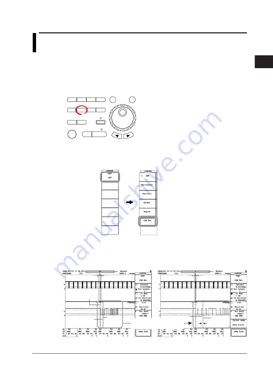
1.
Press
CURSOR
. The CURSOR menu appears.
2.
Press the
Type
soft key. The Type menu appears.
3.
Press the
CAN Bus
soft key.
If you select CAN Bus, Cursor1 moves to the same position as when selecting
Vertical cursor*, but Cursor2 moves to only one bit rate behind that of Cursor1.
(For changing the bit rate and setting the spacing between Cursor1 and
Cursor2, see next page.)
The positions of reference cursors Ref1 and Ref2 remain at their previous settings.
Cursor2
Reference
cursors (Ref1/Ref2)
Cursor1
Cursor2
One bit time
Cursor1
When changing the Z1 Mag
setting value and expanding
this portion
*
For details on cursors other than the CAN Bus signal analysis function cursors, see section
10.5, “Making Cursor Measurements” in the
DL7440/DL7480 User’s Manual (IM701450-01E)
.


