


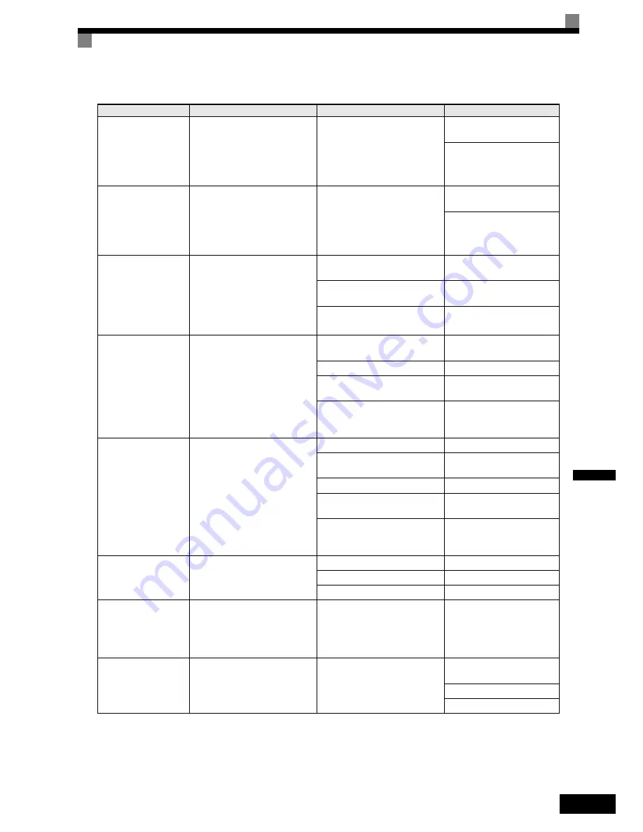
Protective and Diagnostic Functions
6-
5
6
UL3
Undertorq Det 1
Undertorque Detection 1
The Inverter’s output current (V/f
control) or the output torque (Vec-
tor control) fell below L6-02 for
longer then the time set in
L6-03 and L6-04 = 7 or 8.
Motor was underloaded.
Ensure the values in L6-02
and L6-03 are appropriate.
Check application/machine
status to eliminate fault.
UL4
Undertorq Det 2
Undertorque Detection 2
The Inverter’s output current (V/f
control) or the output torque (Vec-
tor control) fell below L6-05 for
longer then the time set in
L6-06 and L6-04 = 7 or 8.
Motor was underloaded.
Ensure the values in L6-05
and L6-06 are appropriate.
Check application/machine
status to eliminate fault.
OS
Overspeed Det
Motor Overspeed
Detected when F1-03 = 0 to 2 and
A1-02 = 1 or 3.
The motor speed feedback
(U1-05) exceeded the setting in
F1-08 for a longer time than the
setting in F1-09.
Overshooting/Undershooting are
occurring.
Adjust the ASR settings in the
C5 parameter group.
The reference was too high.
Check the reference circuit
and reference gain.
The settings in F1-08 and F1-09
are not appropriate.
Check the settings in F1-08
and F1-09.
PGO
PG Open
PG Disconnection
Detected when F1-02 = 0 to 2 and
A1-02 = 1 or 3
Detected when no PG (encoder)
pulses are received for a time
longer than the setting in F1-14.
There is a break in the PG wiring.
Fix the broken/disconnected
wiring.
The PG is wired incorrectly.
Fix the wiring.
Power is not being supplied to
the PG.
Supply power to the PG
properly.
Wrong brake control sequence
when a brake is used.
Check if the brake is opened
when the RUN command is
applied.
DEV
Speed Deviation
Excessive Speed Deviation
Detected when F1-04 = 0 to 2 and
A1-02 = 1 or 3
The speed deviation is greater
than the setting in F1-10 for a
time longer than the setting F1-11
The load is too large.
Reduce the load.
The acceleration time and decel-
eration time are too short.
Lengthen the acceleration
time and deceleration time.
The load is locked.
Check the mechanical system.
The settings in F1-10 and F1-11
are not appropriate.
Check the settings in F1-10
and F1-11.
Wrong brake control sequence
when a brake is used.
Check if the brake is opened
when the RUN command is
applied.
SVE
Zero Servo Fault
Zero Servo Fault
The motor position moved during
Zero Servo Operation.
The torque limit is too small.
Increase the torque limit.
The load torque is too large.
Decrease the load torque.
-
Check for signal noise.
CF
Out of Control
Control Fault
A torque limit was reached con-
tinuously for 3 seconds or longer
during a deceleration stop in Open
Loop Vector control.
Motor parameters were not set
properly.
Check the motor parameters.
EF0
Opt External Flt
External fault input from Com-
munications Option Card
An external fault condition was
present, input from a communica-
tion option card.
Check for an external fault
condition.
Verify the parameters.
Verify communication signals
Table 6.1 Fault Detection (Continued)
Display
Meaning
Probable Causes
Corrective Actions
http://nicontrols.com
Содержание Varispeed L7
Страница 3: ...http nicontrols com...
Страница 55: ...2 30 http nicontrols com...
Страница 129: ...4 62 http nicontrols com...
Страница 197: ...5 68 http nicontrols com...
Страница 219: ...6 22 http nicontrols com...
Страница 243: ...9 14 http nicontrols com...