Basic Operation
6.5.3 PG Speed Control Card Settings
6 - 42
6.5.3 PG Speed Control Card Settings
J
Available PG Speed Control Cards
D
There are 4 models of PG Speed Control Cards, but only 2 models can be used with vector control.
•
PG-A2: Phase-A/Phase-B pulse inputs, complementary output
•
PG-D2: Phase-A/Phase-B/Phase-Z pulse inputs, line drivers
D
Select the Card according to the application and install it in the Inverter as described in
3.7 Installing
and Wiring PG Speed Control Cards
.
J
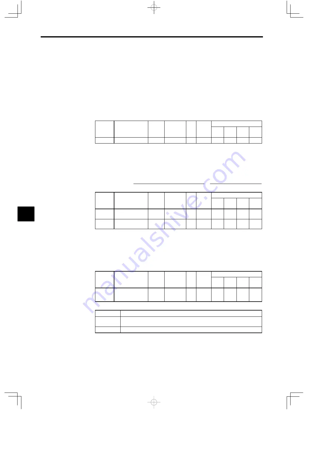
Setting the PG Pulse Number: F1-01
D
Set the PG (pulse generator or encoder) pulse number in pulses/revolution.
D
Set the number of phase A or phase B pulses in one motor revolution.
User
Change
during
Setting
Factory
Valid Access Levels
User
Constant
Number
Name
g
during
Opera-
tion
Setting
Range
Unit Factory
Setting
V/f
Control
V/f with
PG
Open
Loop
Vector
Flux
Vector
F1-01
PG constant
×
0 to 60000
p/r
600
×
Q
×
Q
J
Setting the Number of PG Gear Teeth: F1-12, F1-13
D
When “V/f control with PG feedback” is used, the motor can be operated even if there are gears be-
tween the motor and PG because the responsiveness is lower than it is with vector control.
D
Set the number of teeth on the gears if there are gears between the motor and PG.
D
The motor speed will be calculated within the Inverter using the following equation:
Motor speed (r
∕
min)
=
Number of pulses input from the PG
×
60
Number of PG pulses (F1
−
01)
×
Number of gear teeth 2 (F1
−
13)
Number of gear teeth 1 (F1
−
12)
User
Change
during
Setting
Factory
Valid Access Levels
User
Constant
Number
Name
g
during
Opera-
tion
Setting
Range
Unit Factory
Setting
V/f
Control
V/f with
PG
Open
Loop
Vector
Flux
Vector
F1-12
Number of PG gear
teeth 1
×
0 to 1000
−
0
×
A
×
×
F1-13
Number of PG gear
teeth 2
×
0 to 1000
−
0
×
A
×
×
D
A gear ratio of 1 (F1-12 = F1-13 = 1) will be used if either of these constants is set to 0.
J
Selecting Integral Operation During Acceleration/Deceleration: F1-07
D
When “V/f control with PG feedback” is used, integral control during acceleration and deceleration
can be enabled or disabled with F1-07.
D
Set F1-07 to “1” (integral control enabled) if you want to keep the motor speed as close to the frequency
reference as possible during acceleration and deceleration. Set F1-07 to “0” (integral control disabled)
if you want to prevent the occurrence of overshooting/undershooting.
User
Change
during
Setting
Factory
Valid Access Levels
User
Constant
Number
Name
g
during
Opera-
tion
Setting
Range
Unit Factory
Setting
V/f
Control
V/f with
PG
Open
Loop
Vector
Flux
Vector
F1-07
Integral value during
accel/decel enable/
disable
×
0, 1
−
0
×
B
×
×
D
Settings
Setting
Function
0
Disabled (The integral function isn’t used while accelerating or decelerating; it is used at
constant speeds.)
1
Enabled (The integral function is used at all times.)
J
Setting and Adjusting the Fault Detection Functions
PG Disconnection Stopping Method: F1-02, F1-14
D
This constant sets the stopping method that is used when the signal from the PG is lost.
6
Содержание VARISPEED-616G5
Страница 1: ......


