88
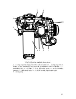
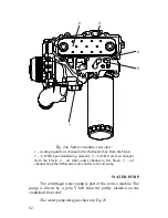
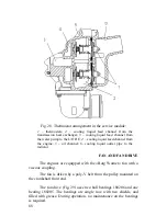
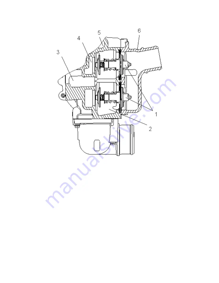
Fig. 28. Thermostat arrangement in the service module:
1
– thermostats;
2
– cooling liquid feed channel from the
transmission heat exchanger;
3
– cooling liquid feed channel from
the water pump to the L/O HE;
4
– cooling liquid feed channel from
the engine;
5
– oil channel;
6
- cooling liquid outlet pipe to the
radiator
FAN AND FAN DRIVE
The engines are equipped with the «Borg Warner» fan with a
viscous coupling.
The fan is driven by a poly-V belt from the pulley mounted on
the crankshaft front end.
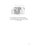
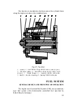
The fan drive (Fig. 29) uses two ball bearings 180206 and one
bearing 180205. The bearings are single row, with two shields, and
filled with grease. During operation, no maintenance on the bearings
is required.
Содержание YMZ-536
Страница 14: ...14 Fig 1 YMZ 536 engine right side view ...
Страница 15: ...15 Fig 1 a YMZ 536 engine left side view ...
Страница 16: ...16 Fig 1 b YMZ 536 10 engine right side view ...
Страница 17: ...17 Fig 1 c YMZ 536 10 engine left side view ...
Страница 18: ...18 Fig 1 d YMZ 536 30 engine right side view ...
Страница 19: ...19 Fig 1 e YMZ 536 30 engine left side view ...
Страница 20: ...20 Fig 1 f YMZ 5362 engine right side view ...
Страница 21: ...21 Fig 1 g YMZ 5362 engine left side view ...
Страница 22: ...22 Fig 1 h YMZ 53602 engine right side view ...
Страница 23: ...23 Fig 1 i YMZ 53602 engine left side view ...
Страница 51: ...51 Fig 10 Longitudinal section ...
Страница 52: ...52 This page intentionally left blank ...
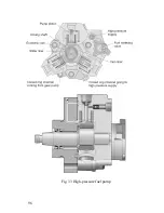
Страница 96: ...96 Fig 33 High pressure fuel pump ...
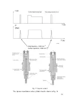
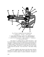
Страница 99: ...99 Fig 35 Injector control The injector installation in the cylinder head is shown in Fig 36 ...
Страница 168: ...168 NOTES ...

