57
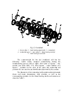
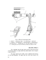
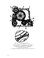
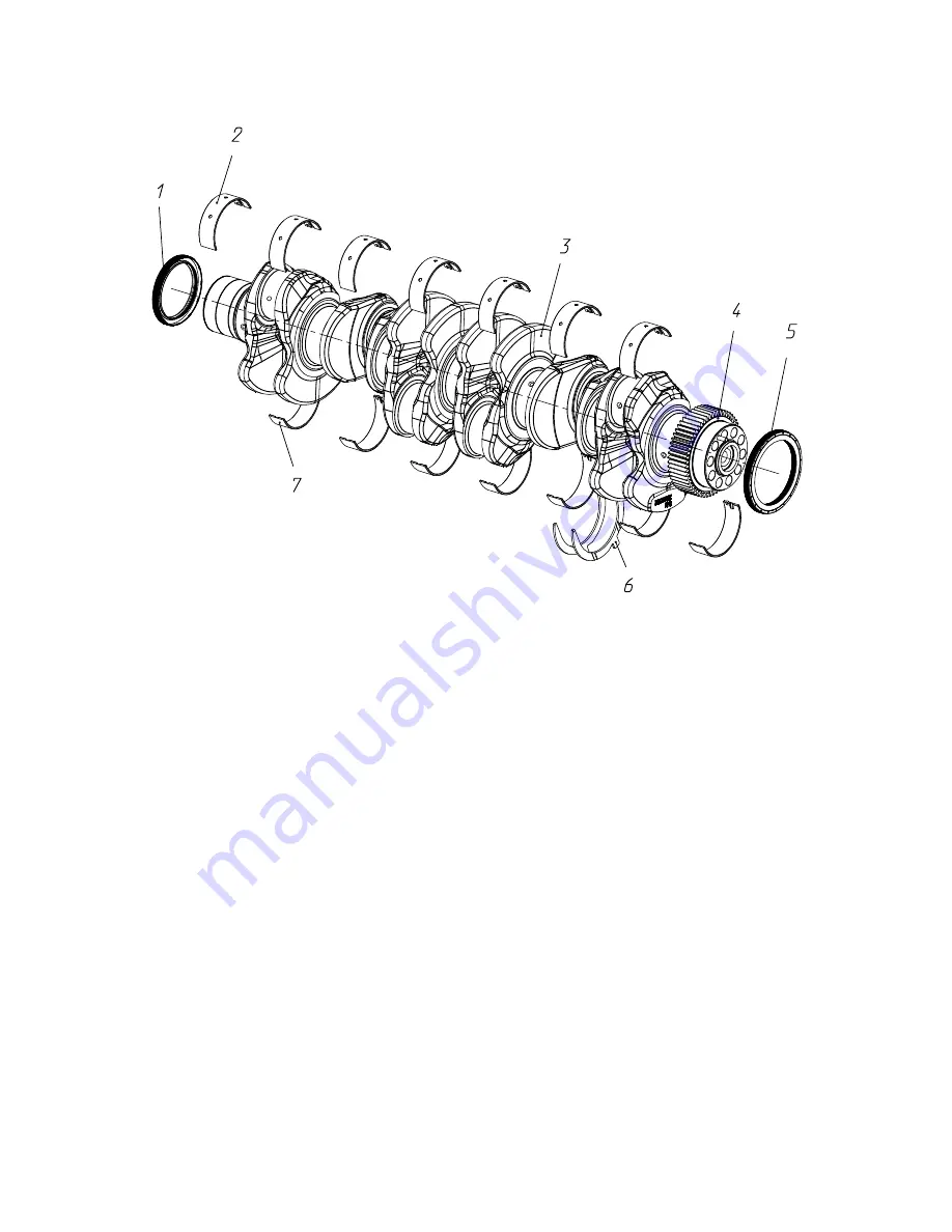
Fig. 12 Crankshaft
1
– front collar;
2
– main bearing upper shell;
3
– crankshaft;
4
– crankshaft gear;
5
– rear collar;
6
– thrust bearing washer;
7
– main bearing lower shell
The counterweight for the last crankshaft web has the
following visible marks stamped automatically during the
manufacturing process (left to right): three pairs of figures – day,
month, year (DD, MM, YY); three figures – serial number; two
figures – symbols for the sizes of the main and connecting rod
journals; the next area has an identification discerned by the scanner.
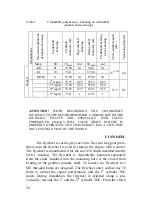
The diameters of the connecting rod journals and main journals
(basic and repair dimensions), their symbols, as well as the
corresponding symbols for the thrust bearing shells and washers are
shown in Table 1.
Содержание YMZ-536
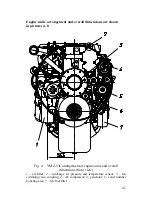
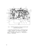
Страница 14: ...14 Fig 1 YMZ 536 engine right side view ...
Страница 15: ...15 Fig 1 a YMZ 536 engine left side view ...
Страница 16: ...16 Fig 1 b YMZ 536 10 engine right side view ...
Страница 17: ...17 Fig 1 c YMZ 536 10 engine left side view ...
Страница 18: ...18 Fig 1 d YMZ 536 30 engine right side view ...
Страница 19: ...19 Fig 1 e YMZ 536 30 engine left side view ...
Страница 20: ...20 Fig 1 f YMZ 5362 engine right side view ...
Страница 21: ...21 Fig 1 g YMZ 5362 engine left side view ...
Страница 22: ...22 Fig 1 h YMZ 53602 engine right side view ...
Страница 23: ...23 Fig 1 i YMZ 53602 engine left side view ...
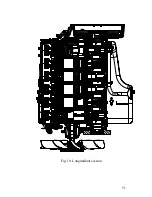
Страница 51: ...51 Fig 10 Longitudinal section ...
Страница 52: ...52 This page intentionally left blank ...
Страница 96: ...96 Fig 33 High pressure fuel pump ...
Страница 99: ...99 Fig 35 Injector control The injector installation in the cylinder head is shown in Fig 36 ...
Страница 168: ...168 NOTES ...


