62
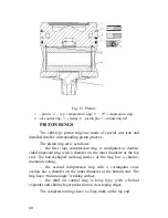
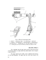
Fig. 14. Piston /Connecting rod unit
1
– piston;
2
– compression rings;
3
– oil control ring;
4
– piston pin;
5
– circlips;
6
– connecting rod;
7
– small end shell;
8
– connecting rod
cap fixing bolts;
9
– marking place for the group number (
А
,
В
,
С
);
10
– marking place for the match marks (numbers from 0001 to 9999)
BEARING SHELLS
The crankshaft main bearing shells and the connecting rod big
end bearing shells are replaceable thin-walled shells with a bronze-
coated steel back.
The upper and the lower shells of the crankshaft main bearing
are not interchangeable. The upper shell has a hole and a groove for
Содержание YMZ-536
Страница 14: ...14 Fig 1 YMZ 536 engine right side view ...
Страница 15: ...15 Fig 1 a YMZ 536 engine left side view ...
Страница 16: ...16 Fig 1 b YMZ 536 10 engine right side view ...
Страница 17: ...17 Fig 1 c YMZ 536 10 engine left side view ...
Страница 18: ...18 Fig 1 d YMZ 536 30 engine right side view ...
Страница 19: ...19 Fig 1 e YMZ 536 30 engine left side view ...
Страница 20: ...20 Fig 1 f YMZ 5362 engine right side view ...
Страница 21: ...21 Fig 1 g YMZ 5362 engine left side view ...
Страница 22: ...22 Fig 1 h YMZ 53602 engine right side view ...
Страница 23: ...23 Fig 1 i YMZ 53602 engine left side view ...
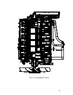
Страница 51: ...51 Fig 10 Longitudinal section ...
Страница 52: ...52 This page intentionally left blank ...
Страница 96: ...96 Fig 33 High pressure fuel pump ...
Страница 99: ...99 Fig 35 Injector control The injector installation in the cylinder head is shown in Fig 36 ...
Страница 168: ...168 NOTES ...

