
60
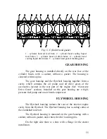
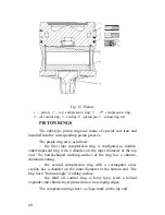
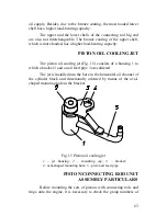
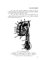
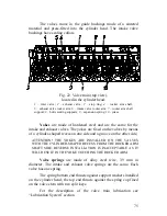
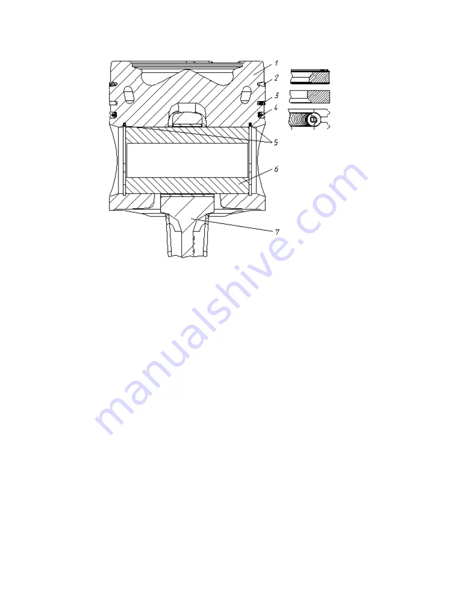
Fig. 13. Piston:
1
– piston;
2
– top compression ring;
3
– 2
nd
compression ring;
4
– oil control ring;
5
– circlips;
6
– piston pin;
7
– connecting rod
PISTON RINGS
The split-type piston rings are made of special cast iron and
installed into the corresponding piston grooves.
The piston ring set is as follows:
the first (top) compression ring is configured as double-
sided trapezoid ring with a chamfer on the inner diameter at the top
end. The barrel-shaped working surface of the ring has a chrome-
diamond coating;
the second compression ring with a rectangular cross
section has a chamfer on the inner diameter at the bottom end. The
ring has a “minute-angle” working surface.
the third oil control ring is boxy type, with a helical
expander and chrome layer protection on its scraping edges.
The compression rings have a «Top» mark on the top end.
Содержание YMZ-536
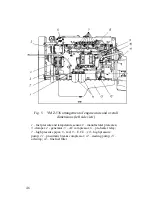
Страница 14: ...14 Fig 1 YMZ 536 engine right side view ...
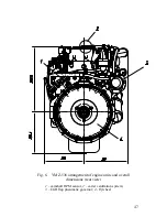
Страница 15: ...15 Fig 1 a YMZ 536 engine left side view ...
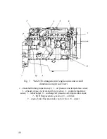
Страница 16: ...16 Fig 1 b YMZ 536 10 engine right side view ...
Страница 17: ...17 Fig 1 c YMZ 536 10 engine left side view ...
Страница 18: ...18 Fig 1 d YMZ 536 30 engine right side view ...
Страница 19: ...19 Fig 1 e YMZ 536 30 engine left side view ...
Страница 20: ...20 Fig 1 f YMZ 5362 engine right side view ...
Страница 21: ...21 Fig 1 g YMZ 5362 engine left side view ...
Страница 22: ...22 Fig 1 h YMZ 53602 engine right side view ...
Страница 23: ...23 Fig 1 i YMZ 53602 engine left side view ...
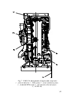
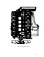
Страница 51: ...51 Fig 10 Longitudinal section ...
Страница 52: ...52 This page intentionally left blank ...
Страница 96: ...96 Fig 33 High pressure fuel pump ...
Страница 99: ...99 Fig 35 Injector control The injector installation in the cylinder head is shown in Fig 36 ...
Страница 168: ...168 NOTES ...


