

82
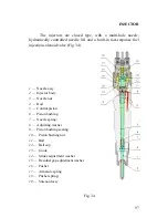
1
2
3
4
5
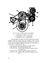
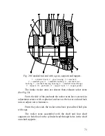
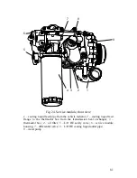
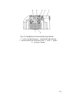
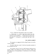
Fig. 24
а
. Service module, rear view:
1
– cooling liquid feed channel to the thermostat box from the block;
2
– L/O HE heat-transferring element;
3
– L/O HE oil feed channel
from the block;
4
– oil filter outlet channel to the block;
5
– oil
channel from the differential valve outlet to the oil sump
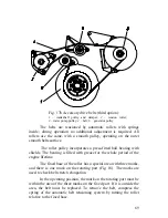
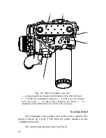
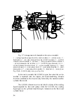
WATER PUMP
The centrifugal water pump is part of the service module. The
pump is driven by a poly-V belt from the pulley installed on the
crankshaft front end.
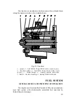
The water pump design is shown in Fig.25.
Содержание YMZ-536
Страница 14: ...14 Fig 1 YMZ 536 engine right side view ...
Страница 15: ...15 Fig 1 a YMZ 536 engine left side view ...
Страница 16: ...16 Fig 1 b YMZ 536 10 engine right side view ...
Страница 17: ...17 Fig 1 c YMZ 536 10 engine left side view ...
Страница 18: ...18 Fig 1 d YMZ 536 30 engine right side view ...
Страница 19: ...19 Fig 1 e YMZ 536 30 engine left side view ...
Страница 20: ...20 Fig 1 f YMZ 5362 engine right side view ...
Страница 21: ...21 Fig 1 g YMZ 5362 engine left side view ...
Страница 22: ...22 Fig 1 h YMZ 53602 engine right side view ...
Страница 23: ...23 Fig 1 i YMZ 53602 engine left side view ...
Страница 51: ...51 Fig 10 Longitudinal section ...
Страница 52: ...52 This page intentionally left blank ...
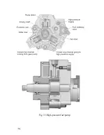
Страница 96: ...96 Fig 33 High pressure fuel pump ...
Страница 99: ...99 Fig 35 Injector control The injector installation in the cylinder head is shown in Fig 36 ...
Страница 168: ...168 NOTES ...


