148
The components used during installation of the vehicle engine
systems must be preserved and packed into a separate box as per
GOST 2991-85.
Engine tools, spare parts and accessories must be preserved,
marked and packed in sets into a separate box as per GOST 2991-85
according to the manufacture’s established procedure.
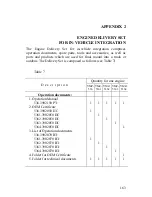
The items which are part of the delivery package must be shipped
together with the engine.
Each box must have a corresponding packing list inside; the
second copy of the packing list must be put into the pocket on the
outside wall of the box.
ENGINE DEPRESERVATION
1.
Unpack the engine and install it onto the vehicle’s chassis
or on the stand.
2.
Remove the packing paper, polyethylene film and
polyethylene tape with adhesive layer from the parts, units
and equipment specified in “Engine Exterior Preservation”
section of this Manual.
3.
Wipe the flywheel surface, the surface of the crankshaft
pulley grooves, the surface of the fan drive, the generator
and the tensioners with a clean cloth wetted with white
spirit to remove completely the protective grease, then wipe
until dry.
4.
Remove the transport plugs.
5.
Install in place the parts which have been removed during
preservation.
6.
When putting the engine into operation, do not perform any
special depreservation if its interior surfaces.
Prepare the engine for start-up according to the procedure described in
the Operation Manual.
Содержание YMZ-536
Страница 14: ...14 Fig 1 YMZ 536 engine right side view ...
Страница 15: ...15 Fig 1 a YMZ 536 engine left side view ...
Страница 16: ...16 Fig 1 b YMZ 536 10 engine right side view ...
Страница 17: ...17 Fig 1 c YMZ 536 10 engine left side view ...
Страница 18: ...18 Fig 1 d YMZ 536 30 engine right side view ...
Страница 19: ...19 Fig 1 e YMZ 536 30 engine left side view ...
Страница 20: ...20 Fig 1 f YMZ 5362 engine right side view ...
Страница 21: ...21 Fig 1 g YMZ 5362 engine left side view ...
Страница 22: ...22 Fig 1 h YMZ 53602 engine right side view ...
Страница 23: ...23 Fig 1 i YMZ 53602 engine left side view ...
Страница 51: ...51 Fig 10 Longitudinal section ...
Страница 52: ...52 This page intentionally left blank ...
Страница 96: ...96 Fig 33 High pressure fuel pump ...
Страница 99: ...99 Fig 35 Injector control The injector installation in the cylinder head is shown in Fig 36 ...
Страница 168: ...168 NOTES ...


