61
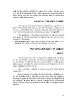
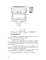
ATTENTION!
WHEN INSTALLING THE PISTON RINGS, PAY
SPECIAL ATTENTION TO THEIR PROPER POSITION. THE
WORD «
ТОР
» MUST FACE THE BOTTOM OF THE PISTON.
PISTON PIN
The piston pin is hollow, floating-type, made of steel with
а
case-hardened surface. The pin is installed into the piston pin hole.
The piston pin axial movement is limited by circlips installed into
special grooves in the piston bosses.
CONNECTING ROD
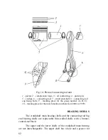
The connecting rod (Fig. 14) is made of steel and has an I-
shaped cross-section. The connecting rod big end has an angle split.
To increase the load-bearing capacity of the connecting rod, the small
end is designed as a taper, with the wider part at the connecting rod
body.
ATTENTION!
THE CONNECTING ROD BIG END HAS AN
ANGLE SPLIT, THEREFORE THE CAPS OF THE CONNECTING RODS
ARE NOT INTERCHANGEABLE. THE PRESENCE OF NICKS OR DIRT
ON THE SPLIT SURFACE IS INACCEPTABLE.
The way the cap is secured to the connecting rod depends on
the split configuration which is different for each connecting rod. In
the joining area, on the long boss side, the cap and the connecting rod
have embossed match marks as a number which is the same for the
connecting rod and the cap (See Fig. 14, View A).
ATTENTION!
ALL CONNECTING RODS ARE DIVIDED INTO
THREE GROUPS ACCORDING TO THEIR WEIGHT. ONLY
CONNECTING RODS BELONGING TO THE SAME WEIGHT GROUP
CAN BE INSTALLED ON THE ENGINE.
The group number: A, B or C, is embossed on the connecting
rod cap.
Into the big end a replaceable shell is installed; into the small
end a steel-bronze bushing is press-fitted. The bushing is machined
after it is press-fitted into the connecting rod.
Содержание YMZ-536
Страница 14: ...14 Fig 1 YMZ 536 engine right side view ...
Страница 15: ...15 Fig 1 a YMZ 536 engine left side view ...
Страница 16: ...16 Fig 1 b YMZ 536 10 engine right side view ...
Страница 17: ...17 Fig 1 c YMZ 536 10 engine left side view ...
Страница 18: ...18 Fig 1 d YMZ 536 30 engine right side view ...
Страница 19: ...19 Fig 1 e YMZ 536 30 engine left side view ...
Страница 20: ...20 Fig 1 f YMZ 5362 engine right side view ...
Страница 21: ...21 Fig 1 g YMZ 5362 engine left side view ...
Страница 22: ...22 Fig 1 h YMZ 53602 engine right side view ...
Страница 23: ...23 Fig 1 i YMZ 53602 engine left side view ...
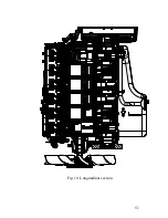
Страница 51: ...51 Fig 10 Longitudinal section ...
Страница 52: ...52 This page intentionally left blank ...
Страница 96: ...96 Fig 33 High pressure fuel pump ...
Страница 99: ...99 Fig 35 Injector control The injector installation in the cylinder head is shown in Fig 36 ...
Страница 168: ...168 NOTES ...

