
59
side the flywheel has «YMZ-536» mark. The flywheel is fixed to the
rear end of the crankshaft with 10 bolts through the common hardened
plate. As the bolts are not locked, they must be properly tightened to
ensure a reliable connection.
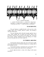
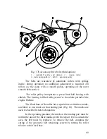
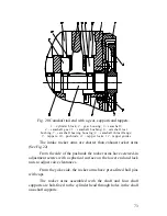
TORSIONAL VIBRATION DAMPER
The liquid-type torsional vibration damper has a pulley for a
poly-V belt incorporated into its rear side. Though the damper is an
accurate and reliable unit, it may be damaged, especially from the
cover side; dents, nicks and overheating may render it inoperable.
The operability of the damper can be checked only on a special
test bench. If properly operated, the damper has a life time not less
than that of the engine.
ATTENTION!
OPERATING THE ENGINE WITH THE DEFECTIVE
DAMPER WILL RESULT IN THE CRANKSHAFT FAILURE
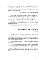
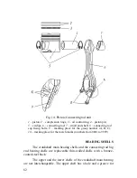
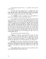
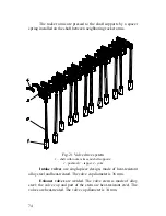
PISTON/CONNECTING ROD
PISTON
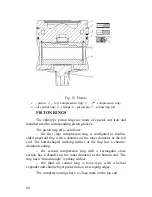
The piston (See Fig.13) is a single-piece design, with 3 grooves
for the piston rings. The groove for the top compression ring is cut in
an insert made of heat-resistant cast iron (Ni-resist). To increase the
piston contact strength, the piston pin bosses are ladder-shaped (the
upper part longer than the lower).
The combustion chamber is central, coaxial with the piston
outer surface.
For the purpose of cooling, the piston head has a closed cavity
for oil circulation. Oil is supplied into the piston from the stationary
injectors mounted on the main oil line of the cylinder block in front of
each piston. The piston has two vertical channels for the oil inlet and
outlet. Near the oil supply channel the piston skirt has a recess for the
injector.
Содержание YMZ-536
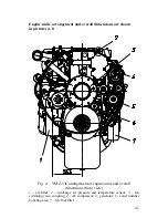
Страница 14: ...14 Fig 1 YMZ 536 engine right side view ...
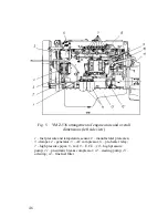
Страница 15: ...15 Fig 1 a YMZ 536 engine left side view ...
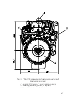
Страница 16: ...16 Fig 1 b YMZ 536 10 engine right side view ...
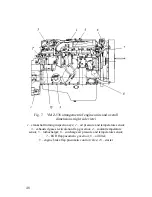
Страница 17: ...17 Fig 1 c YMZ 536 10 engine left side view ...
Страница 18: ...18 Fig 1 d YMZ 536 30 engine right side view ...
Страница 19: ...19 Fig 1 e YMZ 536 30 engine left side view ...
Страница 20: ...20 Fig 1 f YMZ 5362 engine right side view ...
Страница 21: ...21 Fig 1 g YMZ 5362 engine left side view ...
Страница 22: ...22 Fig 1 h YMZ 53602 engine right side view ...
Страница 23: ...23 Fig 1 i YMZ 53602 engine left side view ...
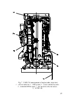
Страница 51: ...51 Fig 10 Longitudinal section ...
Страница 52: ...52 This page intentionally left blank ...
Страница 96: ...96 Fig 33 High pressure fuel pump ...
Страница 99: ...99 Fig 35 Injector control The injector installation in the cylinder head is shown in Fig 36 ...
Страница 168: ...168 NOTES ...


