


4-9
CHAPTER 4 Adjustment
3-4-1
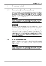
Sensor method
3-4-1-1
YK500XG, YK600XG, YK600XGH, YK700XG, YK800XG,
YK900XG, YK1000XG
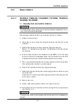
1-1 Adjusting the X-axis machine reference
!
CAUTION
The origin position may change due to machine reference adjustment. If it oc-
curs, you must set point data again.
The adjustment method for the X-axis machine reference is as follows.
1) Prepare a hex wrench set.
2) Check that no one is inside the safeguard enclosure and then turn on the
controller.
3) Perform the absolute reset from outside the safeguard enclosure.
Refer to "3-3 Absolute reset procedures" for information about the absolute
reset method.
4) If any machine reference value displayed on the MPB is not in the range
between 40 and 60 (recommended range) after the absolute reset has been
completed, then proceed with the following adjustment procedure.
5) Place a sign indicating that the robot is being adjusted in order to keep others
from operating the controller or operation panel.
6) Turn off the controller and enter the safeguard enclosure.
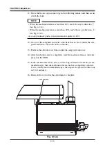
7) Mark off the reference mark at the current origin position on the X-axis joint
area of the robot.
At this time, be careful to prevent the origin position from deviating since the
X-axis arm is touched.
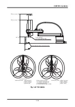
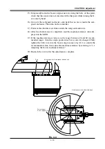
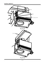
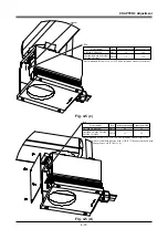
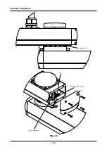
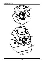
8) Remove the cover.
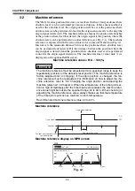
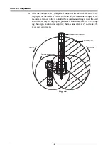
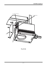
9) Scribe a mark on the position of the X-axis origin sensor stay.
10) Using the hex wrench, loosen the two bolts securing the X-axis origin sensor
stay. (See Fig. 4-3.)
!
CAUTION
The bolts only need to be loosened, and do not need to be completely re-
moved.
Содержание YK-X Series
Страница 1: ...User s Manual ENGLISH E YAMAHA SCARA ROBOT E35 Ver 1 08 YK XG YK X series ...
Страница 2: ......
Страница 6: ...MEMO ...
Страница 10: ...MEMO ...
Страница 12: ...MEMO ...
Страница 29: ...CHAPTER 2 Functions 1 Robot Manipulator 2 1 2 Robot Controller 2 3 3 Robot initialization number list 2 4 ...
Страница 30: ...MEMO ...
Страница 36: ...MEMO ...
Страница 46: ...3 10 CHAPTER 3 Installation Ground symbol M4 Ground terminal Fig 3 6 Ground terminal ...
Страница 64: ...3 28 CHAPTER 3 Installation Hole diameter Bolt Slot Spline shaft End effector or stay Fig 3 27 ...
Страница 78: ...3 42 MEMO ...
Страница 80: ...MEMO ...
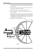
Страница 91: ...4 11 CHAPTER 4 Adjustment X axis origin sensor stay X axis origin sensor Bolt Cover q w Fig 4 3 b ...
Страница 101: ...4 21 CHAPTER 4 Adjustment Cover Elongated hole Y axis origin sensor stay Bolt Fig 4 8 a ...
Страница 102: ...4 22 CHAPTER 4 Adjustment Dog Hex nut Fig 4 8 b Bolt Y axis arm X axis arm Fig 4 8 c ...
Страница 106: ...4 26 CHAPTER 4 Adjustment R axis origin dog Bolt R axis origin sensor stay R axis origin sensor q w Cover Fig 4 9 ...
Страница 119: ...4 39 CHAPTER 4 Adjustment R End effector End effector Z Y X Fig 4 18 ...
Страница 120: ...4 40 MEMO ...
Страница 122: ...MEMO ...
Страница 138: ...5 16 CHAPTER 5 Periodic Inspection M6 16 M5 16 X axis motor Base Fig 5 3 ...
Страница 146: ...5 24 CHAPTER 5 Periodic Inspection M3 16 M4 18 X axis arm Fig 5 10 ...
Страница 155: ...5 33 CHAPTER 5 Periodic Inspection O ring r M5 14 M6 16 R axis motor Fig 5 17 ...
Страница 156: ...5 34 CHAPTER 5 Periodic Inspection M3 14 M3 16 O ring w Fig 5 18 ...
Страница 161: ...CHAPTER 6 Increasing the robot operating speed 1 Increasing the robot operating speed 6 1 ...
Страница 162: ...MEMO ...
Страница 168: ...6 6 MEMO ...
Страница 170: ...MEMO ...
Страница 177: ...MEMO ...


