


3-9
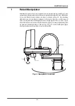
CHAPTER 3 Installation
3
Protective Bonding
WARNING
• Be sure to ground the robot and controller to prevent electrical shock.
• Turn off the controller before grounding the robot.
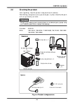
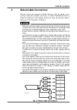
The robot must be grounded as follows:
1) Provide a terminal marked "PE" for the protective conductor of the entire
system and connect it to an external protective conductor. In addition, se-
curely connect the ground terminal on the robot pedestal to the same protec-
tive conductor. (See Fig. 3-6 for example of the YK500XG.)
(Symbol 417-IEC-5019)
2) When the end effector uses an electrical device which, if it malfunctions,
might make contact with the power supply, the user must provide proper
grounding on his own responsibility. The YK-XG series robots do not have a
ground terminal for this purpose.
3) For details on protective bonding on the robot body to comply with CE Mark-
ing, follow the instructions on protective bonding explained in the "YAMAHA
Robot Controller User's Manual" or "CE Marking manual".
4) Use a ground cable with a conductor wire cross section of at least 2.0mm
2
and a length within 1 meter.
Содержание YK-X Series
Страница 1: ...User s Manual ENGLISH E YAMAHA SCARA ROBOT E35 Ver 1 08 YK XG YK X series ...
Страница 2: ......
Страница 6: ...MEMO ...
Страница 10: ...MEMO ...
Страница 12: ...MEMO ...
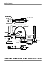
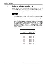
Страница 29: ...CHAPTER 2 Functions 1 Robot Manipulator 2 1 2 Robot Controller 2 3 3 Robot initialization number list 2 4 ...
Страница 30: ...MEMO ...
Страница 36: ...MEMO ...
Страница 46: ...3 10 CHAPTER 3 Installation Ground symbol M4 Ground terminal Fig 3 6 Ground terminal ...
Страница 64: ...3 28 CHAPTER 3 Installation Hole diameter Bolt Slot Spline shaft End effector or stay Fig 3 27 ...
Страница 78: ...3 42 MEMO ...
Страница 80: ...MEMO ...
Страница 91: ...4 11 CHAPTER 4 Adjustment X axis origin sensor stay X axis origin sensor Bolt Cover q w Fig 4 3 b ...
Страница 101: ...4 21 CHAPTER 4 Adjustment Cover Elongated hole Y axis origin sensor stay Bolt Fig 4 8 a ...
Страница 102: ...4 22 CHAPTER 4 Adjustment Dog Hex nut Fig 4 8 b Bolt Y axis arm X axis arm Fig 4 8 c ...
Страница 106: ...4 26 CHAPTER 4 Adjustment R axis origin dog Bolt R axis origin sensor stay R axis origin sensor q w Cover Fig 4 9 ...
Страница 119: ...4 39 CHAPTER 4 Adjustment R End effector End effector Z Y X Fig 4 18 ...
Страница 120: ...4 40 MEMO ...
Страница 122: ...MEMO ...
Страница 138: ...5 16 CHAPTER 5 Periodic Inspection M6 16 M5 16 X axis motor Base Fig 5 3 ...
Страница 146: ...5 24 CHAPTER 5 Periodic Inspection M3 16 M4 18 X axis arm Fig 5 10 ...
Страница 155: ...5 33 CHAPTER 5 Periodic Inspection O ring r M5 14 M6 16 R axis motor Fig 5 17 ...
Страница 156: ...5 34 CHAPTER 5 Periodic Inspection M3 14 M3 16 O ring w Fig 5 18 ...
Страница 161: ...CHAPTER 6 Increasing the robot operating speed 1 Increasing the robot operating speed 6 1 ...
Страница 162: ...MEMO ...
Страница 168: ...6 6 MEMO ...
Страница 170: ...MEMO ...
Страница 177: ...MEMO ...


