


3-22
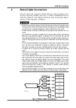
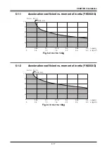
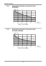
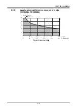
CHAPTER 3 Installation
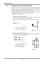
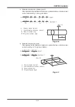
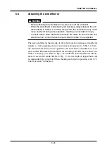
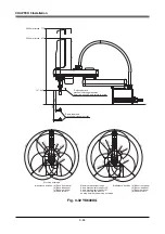
5) When the object's center line is offset from the rotation center.
The equation for the moment of inertia, when the center of the cylinder is
offset by the distance "x" from the rotation center as shown in Fig. 3-18, is
given as follows.
D
h
J=
ρπ
D h
32g
WD
8g
=
4
2
... (Eq. 3.5)
x
+
ρπ
D hx
4g
2
+
Wx
g
2
Center line
Rotation center
2
I=
ρπ
D h
32
4
+
ρπ
D hx
4
2
2
mD
8
=
2
mx
2
+
ρ
: Density (kg/m
3
, kg/cm
3
)
g : Gravitational acceleration (cm/sec
2
)
m : Mass of cylinder (kg)
W : Weight of cylinder (kgf)
(kgfcmsec
2
)
(kgm
2
)
Fig. 3-18
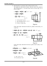
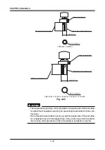
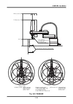
In the same manner, the moment of inertia of a cylinder as shown in Fig. 3-19
is given by
W
4g
=
... (Eq. 3.6)
D
4
h
3
(
2
2
+
)
h
D
x
Cneter line
J=
ρπ
D h
16g
+
2
D
4
h
3
(
2
2
+
)
ρπ
D h x
4g
2
2
+
Wx
g
2
I=
ρπ
D h
16
+
2
D
4
h
3
(
2
2
+
)
ρπ
D h x
4
2
2
m
4
=
D
4
h
3
(
2
2
+
) + mx
2
(kgfcmsec
2
)
(kgm
2
)
Fig. 3-19
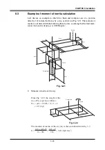
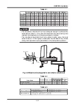
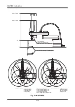
In the same manner, the moment of inertia of a prism as shown in Fig. 3-20 is
given by
J=
ρ
abc(a + b )
12g
W(a + b )
12g
=
2
2
... (Eq. 3.7)
2
2
+
ρ
abcx
g
Wx
g
+
2
2
a
c
b
x
Center line
I=
ρ
abc(a + b )
12
2
2
+
ρ
abcx
2
=
m(a +b )
12
2
2
+ mx
2
m : Mass of prism (kg)
W : Weight of prism (kgf)
(kgfcmsec
2
)
(kgm
2
)
Fig. 3-20
Содержание YK-X Series
Страница 1: ...User s Manual ENGLISH E YAMAHA SCARA ROBOT E35 Ver 1 08 YK XG YK X series ...
Страница 2: ......
Страница 6: ...MEMO ...
Страница 10: ...MEMO ...
Страница 12: ...MEMO ...
Страница 29: ...CHAPTER 2 Functions 1 Robot Manipulator 2 1 2 Robot Controller 2 3 3 Robot initialization number list 2 4 ...
Страница 30: ...MEMO ...
Страница 36: ...MEMO ...
Страница 46: ...3 10 CHAPTER 3 Installation Ground symbol M4 Ground terminal Fig 3 6 Ground terminal ...
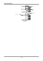
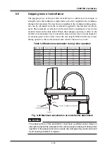
Страница 64: ...3 28 CHAPTER 3 Installation Hole diameter Bolt Slot Spline shaft End effector or stay Fig 3 27 ...
Страница 78: ...3 42 MEMO ...
Страница 80: ...MEMO ...
Страница 91: ...4 11 CHAPTER 4 Adjustment X axis origin sensor stay X axis origin sensor Bolt Cover q w Fig 4 3 b ...
Страница 101: ...4 21 CHAPTER 4 Adjustment Cover Elongated hole Y axis origin sensor stay Bolt Fig 4 8 a ...
Страница 102: ...4 22 CHAPTER 4 Adjustment Dog Hex nut Fig 4 8 b Bolt Y axis arm X axis arm Fig 4 8 c ...
Страница 106: ...4 26 CHAPTER 4 Adjustment R axis origin dog Bolt R axis origin sensor stay R axis origin sensor q w Cover Fig 4 9 ...
Страница 119: ...4 39 CHAPTER 4 Adjustment R End effector End effector Z Y X Fig 4 18 ...
Страница 120: ...4 40 MEMO ...
Страница 122: ...MEMO ...
Страница 138: ...5 16 CHAPTER 5 Periodic Inspection M6 16 M5 16 X axis motor Base Fig 5 3 ...
Страница 146: ...5 24 CHAPTER 5 Periodic Inspection M3 16 M4 18 X axis arm Fig 5 10 ...
Страница 155: ...5 33 CHAPTER 5 Periodic Inspection O ring r M5 14 M6 16 R axis motor Fig 5 17 ...
Страница 156: ...5 34 CHAPTER 5 Periodic Inspection M3 14 M3 16 O ring w Fig 5 18 ...
Страница 161: ...CHAPTER 6 Increasing the robot operating speed 1 Increasing the robot operating speed 6 1 ...
Страница 162: ...MEMO ...
Страница 168: ...6 6 MEMO ...
Страница 170: ...MEMO ...
Страница 177: ...MEMO ...


