


4-27
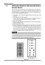
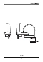
CHAPTER 4 Adjustment
3-4-2
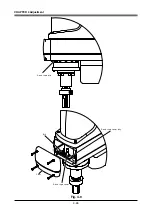
Stroke end method
The stroke end method is employed on the YK-XG series robots for the absolute
reset of the Z-axis. The origin position of the Z-axis is fixed at the upper end of
the Z-axis stroke, and it cannot be changed. The machine reference is factory-
adjusted at shipment, and readjustment is not necessary for normal use. The read-
justment in the following procedure is required, however, if the machine refer-
ence exceeds the tolerance range (33 to 67) of the absolute reset for any reason.
!
CAUTION
The origin position may change due to machine reference adjustment. If it occurs,
you must set point data again.
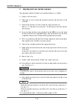
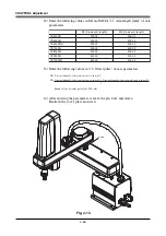
3-4-2-1
YK500XG, YK600XG, YK600XGH, YK700XG, YK800XG,
YK900XG, YK1000XG
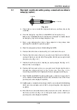
1) Check that no one is inside the safeguard enclosure, and then turn on the
controller.
2) Place a sign indicating the robot is being adjusted, to keep others from oper-
ating the controller or operation panel.
3) Perform the Z-axis absolute reset.
To perform the Z-axis absolute reset, see "3-3 Absolute reset procedures" in
Chapter 4. Make a note of the Z-axis machine reference value.
!
CAUTION
Use the following procedure to display the
adjustment machine reference
value
.
When
adjusting the machine reference value
, always check the
adjustment
machine reference value
with this procedure.
(1) Press the MODE key.
(2) Press the F3 key to enter MANUAL mode.
(3) Press the F13 key (LOWER+F3) to select "ABS Reset".
(4) After the Z-axis absolute reset is complete, press the F10 (UPPER+F5) key
to display the
adjustment machine reference value (%)
.
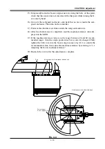
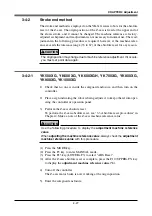
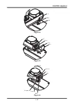
4) Turn off the controller.
The Z-axis motor brake is now working at the origin position.
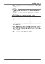
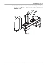
5) Enter the safeguard enclosure.
Содержание YK-X Series
Страница 1: ...User s Manual ENGLISH E YAMAHA SCARA ROBOT E35 Ver 1 08 YK XG YK X series ...
Страница 2: ......
Страница 6: ...MEMO ...
Страница 10: ...MEMO ...
Страница 12: ...MEMO ...
Страница 29: ...CHAPTER 2 Functions 1 Robot Manipulator 2 1 2 Robot Controller 2 3 3 Robot initialization number list 2 4 ...
Страница 30: ...MEMO ...
Страница 36: ...MEMO ...
Страница 46: ...3 10 CHAPTER 3 Installation Ground symbol M4 Ground terminal Fig 3 6 Ground terminal ...
Страница 64: ...3 28 CHAPTER 3 Installation Hole diameter Bolt Slot Spline shaft End effector or stay Fig 3 27 ...
Страница 78: ...3 42 MEMO ...
Страница 80: ...MEMO ...
Страница 91: ...4 11 CHAPTER 4 Adjustment X axis origin sensor stay X axis origin sensor Bolt Cover q w Fig 4 3 b ...
Страница 101: ...4 21 CHAPTER 4 Adjustment Cover Elongated hole Y axis origin sensor stay Bolt Fig 4 8 a ...
Страница 102: ...4 22 CHAPTER 4 Adjustment Dog Hex nut Fig 4 8 b Bolt Y axis arm X axis arm Fig 4 8 c ...
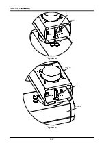
Страница 106: ...4 26 CHAPTER 4 Adjustment R axis origin dog Bolt R axis origin sensor stay R axis origin sensor q w Cover Fig 4 9 ...
Страница 119: ...4 39 CHAPTER 4 Adjustment R End effector End effector Z Y X Fig 4 18 ...
Страница 120: ...4 40 MEMO ...
Страница 122: ...MEMO ...
Страница 138: ...5 16 CHAPTER 5 Periodic Inspection M6 16 M5 16 X axis motor Base Fig 5 3 ...
Страница 146: ...5 24 CHAPTER 5 Periodic Inspection M3 16 M4 18 X axis arm Fig 5 10 ...
Страница 155: ...5 33 CHAPTER 5 Periodic Inspection O ring r M5 14 M6 16 R axis motor Fig 5 17 ...
Страница 156: ...5 34 CHAPTER 5 Periodic Inspection M3 14 M3 16 O ring w Fig 5 18 ...
Страница 161: ...CHAPTER 6 Increasing the robot operating speed 1 Increasing the robot operating speed 6 1 ...
Страница 162: ...MEMO ...
Страница 168: ...6 6 MEMO ...
Страница 170: ...MEMO ...
Страница 177: ...MEMO ...


