CHAPTER 2 Functions
2-4
3
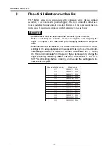
Robot initialization number list
The YK-XG series robots are initialized for optimum setting (default setting)
according to the robot model prior to shipping. The robot controllers do not have
to be reinitialized during normal operation. However, if for some reason the con-
troller must be reinitialized, proceed while referring to the list below.
!
CAUTION
• Absolute reset must be performed after reinitializing the controller.
Before reinitializing the controller, read the descriptions in "3. Adjusting the
origin" in Chapter 4 and make sure you thoroughly understand the proce-
dure.
• When the controller is initialized, the "ARM LENGTH" and "OFFSET PULSE"
settings in the axis parameters will be erased, making the standard coordi-
nate settings invalid. (For details on standard coordinates, see "5. Setting
the Standard Coordinates" in Chapter 4.) If you do not want to change the
origin position by initializing, make a note of the "ARM LENGTH" and "OFF-
SET PULSE" settings before initializing, and re-enter their settings after ini-
tialization is complete.
Robot initialization number
2117
2118
2119
2120
2121
2122
2123
2124
2125
2126
2127
2128
2129
2130
Model name
YK500XG Z200
YK500XG Z300
YK600XG Z200
YK600XG Z300
YK600XGH Z200
YK600XGH Z400
YK700XG Z200
YK700XG Z400
YK800XG Z200
YK800XG Z400
YK900XG Z200
YK900XG Z400
YK1000XG Z200
YK1000XG Z400
Содержание YK-X Series
Страница 1: ...User s Manual ENGLISH E YAMAHA SCARA ROBOT E35 Ver 1 08 YK XG YK X series ...
Страница 2: ......
Страница 6: ...MEMO ...
Страница 10: ...MEMO ...
Страница 12: ...MEMO ...
Страница 29: ...CHAPTER 2 Functions 1 Robot Manipulator 2 1 2 Robot Controller 2 3 3 Robot initialization number list 2 4 ...
Страница 30: ...MEMO ...
Страница 36: ...MEMO ...
Страница 46: ...3 10 CHAPTER 3 Installation Ground symbol M4 Ground terminal Fig 3 6 Ground terminal ...
Страница 64: ...3 28 CHAPTER 3 Installation Hole diameter Bolt Slot Spline shaft End effector or stay Fig 3 27 ...
Страница 78: ...3 42 MEMO ...
Страница 80: ...MEMO ...
Страница 91: ...4 11 CHAPTER 4 Adjustment X axis origin sensor stay X axis origin sensor Bolt Cover q w Fig 4 3 b ...
Страница 101: ...4 21 CHAPTER 4 Adjustment Cover Elongated hole Y axis origin sensor stay Bolt Fig 4 8 a ...
Страница 102: ...4 22 CHAPTER 4 Adjustment Dog Hex nut Fig 4 8 b Bolt Y axis arm X axis arm Fig 4 8 c ...
Страница 106: ...4 26 CHAPTER 4 Adjustment R axis origin dog Bolt R axis origin sensor stay R axis origin sensor q w Cover Fig 4 9 ...
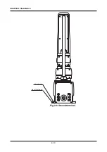
Страница 119: ...4 39 CHAPTER 4 Adjustment R End effector End effector Z Y X Fig 4 18 ...
Страница 120: ...4 40 MEMO ...
Страница 122: ...MEMO ...
Страница 138: ...5 16 CHAPTER 5 Periodic Inspection M6 16 M5 16 X axis motor Base Fig 5 3 ...
Страница 146: ...5 24 CHAPTER 5 Periodic Inspection M3 16 M4 18 X axis arm Fig 5 10 ...
Страница 155: ...5 33 CHAPTER 5 Periodic Inspection O ring r M5 14 M6 16 R axis motor Fig 5 17 ...
Страница 156: ...5 34 CHAPTER 5 Periodic Inspection M3 14 M3 16 O ring w Fig 5 18 ...
Страница 161: ...CHAPTER 6 Increasing the robot operating speed 1 Increasing the robot operating speed 6 1 ...
Страница 162: ...MEMO ...
Страница 168: ...6 6 MEMO ...
Страница 170: ...MEMO ...
Страница 177: ...MEMO ...


