5-28
CHAPTER 5 Periodic Inspection
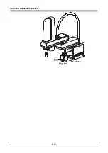
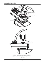
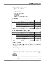
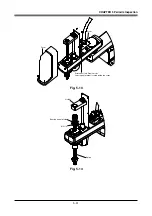
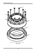
6) Remove the bolts securing the bearing to the upper end of the spline and
remove the spline and bearing from the holder. (See Fig. 5-14.)
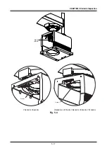
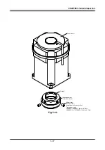
7) Fit the spanner or wrench to the flat surfaces at the bottom of the spline to
grip it, and loosen and remove the U-nut on top of the spline with the hook
spanner. Then remove the bearing and bearing mount plate. (See Figs. 5-15
and 5-16.)
At this point, be careful to keep the spline shaft from coming off the spline
nut.
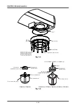
8) Remove the bolts securing the spline nut and remove the spline nut.
(See Fig. 5-16.)
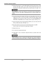
!
CAUTION
An O-ring
e
is fitted to the shaft. Replace this O-ring with a new one. Also
replace the V-ring with a new one. Do not remove the sleeve. (See Fig. 5-16.)
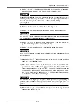
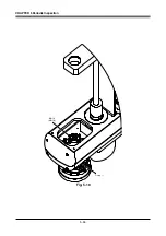
9) Remove the bolts securing the R-axis motor and pull out the R-axis motor
while turning the R-axis. (See Fig. 5-17.)
!
CAUTION
An O-ring
r
is placed between the R-axis motor flange and the Y-axis arm.
Replace this O-ring with a new one. (See Fig. 5-17.)
10) Loosen the two setscrews for the wave generator.
Pull the wave generator out of the R-axis motor shaft. (See Fig. 5-20.)
!
CAUTION
An O-ring
t
is placed between the R-axis motor shaft and the wave generator.
Replace this O-ring with a new one. (See Fig. 5-20.)
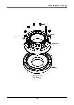
11) Remove the bolts securing the harmonic drive and remove the harmonic drive.
(See Fig. 5-18.)
!
CAUTION
An O-ring
w
is fitted to the harmonic drive. Replace this O-ring with a new one.
(See Fig. 5-18.)
12) Remove the shaft mounting bolts from the harmonic drive and also remove
the panhead bolt along with the nut. Then remove the shaft.
On the YK600XGH and YK700XG to YK1000XG, remove the dog and bolt.
(See Fig. 5-19 (b).)
!
CAUTION
An O-ring
q
is placed between the harmonic drive and shaft. Replace this O-
ring with a new one. (See Fig. 5-19 (a) (b).)
Содержание YK-X Series
Страница 1: ...User s Manual ENGLISH E YAMAHA SCARA ROBOT E35 Ver 1 08 YK XG YK X series ...
Страница 2: ......
Страница 6: ...MEMO ...
Страница 10: ...MEMO ...
Страница 12: ...MEMO ...
Страница 29: ...CHAPTER 2 Functions 1 Robot Manipulator 2 1 2 Robot Controller 2 3 3 Robot initialization number list 2 4 ...
Страница 30: ...MEMO ...
Страница 36: ...MEMO ...
Страница 46: ...3 10 CHAPTER 3 Installation Ground symbol M4 Ground terminal Fig 3 6 Ground terminal ...
Страница 64: ...3 28 CHAPTER 3 Installation Hole diameter Bolt Slot Spline shaft End effector or stay Fig 3 27 ...
Страница 78: ...3 42 MEMO ...
Страница 80: ...MEMO ...
Страница 91: ...4 11 CHAPTER 4 Adjustment X axis origin sensor stay X axis origin sensor Bolt Cover q w Fig 4 3 b ...
Страница 101: ...4 21 CHAPTER 4 Adjustment Cover Elongated hole Y axis origin sensor stay Bolt Fig 4 8 a ...
Страница 102: ...4 22 CHAPTER 4 Adjustment Dog Hex nut Fig 4 8 b Bolt Y axis arm X axis arm Fig 4 8 c ...
Страница 106: ...4 26 CHAPTER 4 Adjustment R axis origin dog Bolt R axis origin sensor stay R axis origin sensor q w Cover Fig 4 9 ...
Страница 119: ...4 39 CHAPTER 4 Adjustment R End effector End effector Z Y X Fig 4 18 ...
Страница 120: ...4 40 MEMO ...
Страница 122: ...MEMO ...
Страница 138: ...5 16 CHAPTER 5 Periodic Inspection M6 16 M5 16 X axis motor Base Fig 5 3 ...
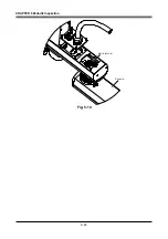
Страница 146: ...5 24 CHAPTER 5 Periodic Inspection M3 16 M4 18 X axis arm Fig 5 10 ...
Страница 155: ...5 33 CHAPTER 5 Periodic Inspection O ring r M5 14 M6 16 R axis motor Fig 5 17 ...
Страница 156: ...5 34 CHAPTER 5 Periodic Inspection M3 14 M3 16 O ring w Fig 5 18 ...
Страница 161: ...CHAPTER 6 Increasing the robot operating speed 1 Increasing the robot operating speed 6 1 ...
Страница 162: ...MEMO ...
Страница 168: ...6 6 MEMO ...
Страница 170: ...MEMO ...
Страница 177: ...MEMO ...


