


3-39
CHAPTER 3 Installation
990
790
12
400
12
0
208.7±2
200
0
6
132
°
130
°
150
°
150
°
R1000
R229 (a)
R191 (d)
130
°
R165 (b)
R323
R400
150
°
150
°
R134 (c)
132
°
152
°
152
°
R1000
R215 (a)
R180(d)
R149 (b)
152
°
152
°
R310
R400
R120 (c)
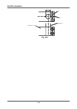
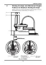
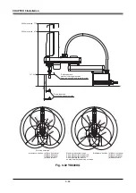
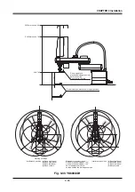
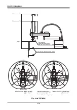
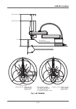
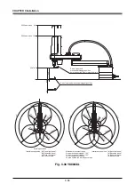
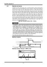
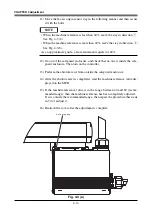
Z400mm stroke
Z200mm stroke
Z-axis upper-end
mechanical stopper position
6mm rise during Z-axis return-to-origin
Z-axis lower end mechanical stopper position
Working envelope
Interference position (a) Base front panel
(b) Base side panel
(c) Base rear panel
(d) Base corners
Interference position (a) Base front panel
(b) Base side panel
(c) Base rear panel
(d) Base corners
Maximum movement range
X-axis mechanical stopper: 132°
Y-axis mechanical stopper: 152°
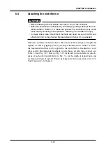
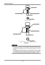
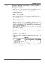
Do not operate the robot in
an area outside the working envelope.
Fig. 3-37 YK1000XG
Содержание YK-X Series
Страница 1: ...User s Manual ENGLISH E YAMAHA SCARA ROBOT E35 Ver 1 08 YK XG YK X series ...
Страница 2: ......
Страница 6: ...MEMO ...
Страница 10: ...MEMO ...
Страница 12: ...MEMO ...
Страница 29: ...CHAPTER 2 Functions 1 Robot Manipulator 2 1 2 Robot Controller 2 3 3 Robot initialization number list 2 4 ...
Страница 30: ...MEMO ...
Страница 36: ...MEMO ...
Страница 46: ...3 10 CHAPTER 3 Installation Ground symbol M4 Ground terminal Fig 3 6 Ground terminal ...
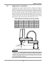
Страница 64: ...3 28 CHAPTER 3 Installation Hole diameter Bolt Slot Spline shaft End effector or stay Fig 3 27 ...
Страница 78: ...3 42 MEMO ...
Страница 80: ...MEMO ...
Страница 91: ...4 11 CHAPTER 4 Adjustment X axis origin sensor stay X axis origin sensor Bolt Cover q w Fig 4 3 b ...
Страница 101: ...4 21 CHAPTER 4 Adjustment Cover Elongated hole Y axis origin sensor stay Bolt Fig 4 8 a ...
Страница 102: ...4 22 CHAPTER 4 Adjustment Dog Hex nut Fig 4 8 b Bolt Y axis arm X axis arm Fig 4 8 c ...
Страница 106: ...4 26 CHAPTER 4 Adjustment R axis origin dog Bolt R axis origin sensor stay R axis origin sensor q w Cover Fig 4 9 ...
Страница 119: ...4 39 CHAPTER 4 Adjustment R End effector End effector Z Y X Fig 4 18 ...
Страница 120: ...4 40 MEMO ...
Страница 122: ...MEMO ...
Страница 138: ...5 16 CHAPTER 5 Periodic Inspection M6 16 M5 16 X axis motor Base Fig 5 3 ...
Страница 146: ...5 24 CHAPTER 5 Periodic Inspection M3 16 M4 18 X axis arm Fig 5 10 ...
Страница 155: ...5 33 CHAPTER 5 Periodic Inspection O ring r M5 14 M6 16 R axis motor Fig 5 17 ...
Страница 156: ...5 34 CHAPTER 5 Periodic Inspection M3 14 M3 16 O ring w Fig 5 18 ...
Страница 161: ...CHAPTER 6 Increasing the robot operating speed 1 Increasing the robot operating speed 6 1 ...
Страница 162: ...MEMO ...
Страница 168: ...6 6 MEMO ...
Страница 170: ...MEMO ...
Страница 177: ...MEMO ...


