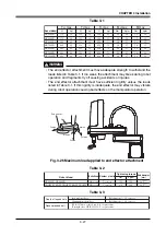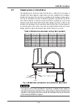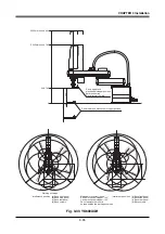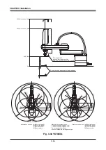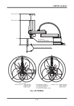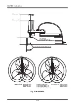
3-26
CHAPTER 3 Installation
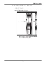
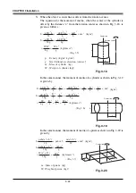
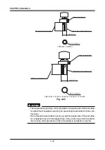
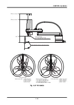
Never loosen this bolt.
Spline shaft (hollow diameter
φ
14)
φ
20 h7
0
-0.021
End effector attachment area
40
M16
×
2, depth 20
YK500XG, YK600XG
Never loosen this bolt.
Spline shaft (hollow diameter
φ
18)
45
φ
25 h7
0
-0.021
M20
×
2.5, depth 20
YK600XGH, YK700XG, YK800XG, YK900XG, YK1000XG
End effector attachment area
Fig. 3-25
WARNING
• The tapped hole (see Figs. 3-25) provided on the lower part of the end effec-
tor attachment should be used only for preventing the end effector from com-
ing loose.
• Do not fasten the end effector just by using this tapped hole. If the end effec-
tor is fastened only with this tapped hole, it may come loose from the attach-
ment during robot operation and fly off resulting in accidents or injuries.
Содержание YK-X Series
Страница 1: ...User s Manual ENGLISH E YAMAHA SCARA ROBOT E35 Ver 1 08 YK XG YK X series ...
Страница 2: ......
Страница 6: ...MEMO ...
Страница 10: ...MEMO ...
Страница 12: ...MEMO ...
Страница 29: ...CHAPTER 2 Functions 1 Robot Manipulator 2 1 2 Robot Controller 2 3 3 Robot initialization number list 2 4 ...
Страница 30: ...MEMO ...
Страница 36: ...MEMO ...
Страница 46: ...3 10 CHAPTER 3 Installation Ground symbol M4 Ground terminal Fig 3 6 Ground terminal ...
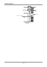
Страница 64: ...3 28 CHAPTER 3 Installation Hole diameter Bolt Slot Spline shaft End effector or stay Fig 3 27 ...
Страница 78: ...3 42 MEMO ...
Страница 80: ...MEMO ...
Страница 91: ...4 11 CHAPTER 4 Adjustment X axis origin sensor stay X axis origin sensor Bolt Cover q w Fig 4 3 b ...
Страница 101: ...4 21 CHAPTER 4 Adjustment Cover Elongated hole Y axis origin sensor stay Bolt Fig 4 8 a ...
Страница 102: ...4 22 CHAPTER 4 Adjustment Dog Hex nut Fig 4 8 b Bolt Y axis arm X axis arm Fig 4 8 c ...
Страница 106: ...4 26 CHAPTER 4 Adjustment R axis origin dog Bolt R axis origin sensor stay R axis origin sensor q w Cover Fig 4 9 ...
Страница 119: ...4 39 CHAPTER 4 Adjustment R End effector End effector Z Y X Fig 4 18 ...
Страница 120: ...4 40 MEMO ...
Страница 122: ...MEMO ...
Страница 138: ...5 16 CHAPTER 5 Periodic Inspection M6 16 M5 16 X axis motor Base Fig 5 3 ...
Страница 146: ...5 24 CHAPTER 5 Periodic Inspection M3 16 M4 18 X axis arm Fig 5 10 ...
Страница 155: ...5 33 CHAPTER 5 Periodic Inspection O ring r M5 14 M6 16 R axis motor Fig 5 17 ...
Страница 156: ...5 34 CHAPTER 5 Periodic Inspection M3 14 M3 16 O ring w Fig 5 18 ...
Страница 161: ...CHAPTER 6 Increasing the robot operating speed 1 Increasing the robot operating speed 6 1 ...
Страница 162: ...MEMO ...
Страница 168: ...6 6 MEMO ...
Страница 170: ...MEMO ...
Страница 177: ...MEMO ...

