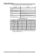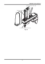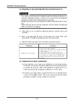
4-35
CHAPTER 4 Adjustment
5-1
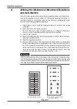
Standard coordinate setting using a standard coordinate
setup jig (option)
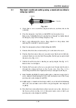
+Y direction
+X direction
Fig. 4-12
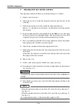
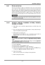
1) Check that no one is inside the safeguard enclosure, and then turn on the
controller.
2) Press the emergency stop button on the MPB to set emergency stop.
Refer to the "YAMAHA Robot Controller User's Manual" for further details
on emergency stop and canceling emergency stop.
3) Place a sign indicating the robot is being adjusted, to keep others from
operating the controller or operation panel.
4) Enter the safeguard enclosure while holding the MPB.
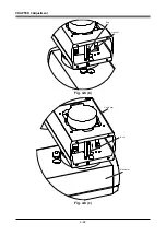
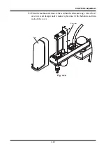
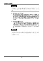
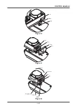
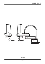
5) Position the robot arms as shown in Fig. 4-13 and remove the screw.
6) Position the robot arms so that you can easily insert the sleeve into the hole,
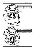
and insert the sleeve into the hole. Then tighten the bolt just enough to hold
the sleeve. (See Fig. 4-14.)
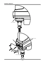
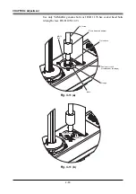
7) Turn the X and Y-axis arms so that they are nearly straight. (See Fig. 4-15.)
Remove the cover and plate.
8) Position the Y-axis arm so that you can easily insert the pin into the sleeve
through the elongated hole in the Y-axis arm. (See Fig. 4-16.)
Secure the pin with the bolt. Tighten the bolt just enough to hold the pin.
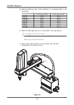
9) Enter "MANUAL>POINT" mode. Lightly apply a clockwise torque to the Y-
axis to unload it while holding the X-axis arm, and make a note of the Y-axis
position pulse value displayed on [POS].
10) Lightly apply a counterclockwise torque to the Y-axis to unload it while holding
the X-axis arm, and make a note of the Y-axis position pulse value displayed
on [POS].
11) Move the X-axis arm in the direction that you want to set as the + direction of
the X-axis as shown in Fig. 4-12. At this point, make a note of the X-axis
position pulse value displayed on [POS].
Содержание YK-X Series
Страница 1: ...User s Manual ENGLISH E YAMAHA SCARA ROBOT E35 Ver 1 08 YK XG YK X series ...
Страница 2: ......
Страница 6: ...MEMO ...
Страница 10: ...MEMO ...
Страница 12: ...MEMO ...
Страница 29: ...CHAPTER 2 Functions 1 Robot Manipulator 2 1 2 Robot Controller 2 3 3 Robot initialization number list 2 4 ...
Страница 30: ...MEMO ...
Страница 36: ...MEMO ...
Страница 46: ...3 10 CHAPTER 3 Installation Ground symbol M4 Ground terminal Fig 3 6 Ground terminal ...
Страница 64: ...3 28 CHAPTER 3 Installation Hole diameter Bolt Slot Spline shaft End effector or stay Fig 3 27 ...
Страница 78: ...3 42 MEMO ...
Страница 80: ...MEMO ...
Страница 91: ...4 11 CHAPTER 4 Adjustment X axis origin sensor stay X axis origin sensor Bolt Cover q w Fig 4 3 b ...
Страница 101: ...4 21 CHAPTER 4 Adjustment Cover Elongated hole Y axis origin sensor stay Bolt Fig 4 8 a ...
Страница 102: ...4 22 CHAPTER 4 Adjustment Dog Hex nut Fig 4 8 b Bolt Y axis arm X axis arm Fig 4 8 c ...
Страница 106: ...4 26 CHAPTER 4 Adjustment R axis origin dog Bolt R axis origin sensor stay R axis origin sensor q w Cover Fig 4 9 ...
Страница 119: ...4 39 CHAPTER 4 Adjustment R End effector End effector Z Y X Fig 4 18 ...
Страница 120: ...4 40 MEMO ...
Страница 122: ...MEMO ...
Страница 138: ...5 16 CHAPTER 5 Periodic Inspection M6 16 M5 16 X axis motor Base Fig 5 3 ...
Страница 146: ...5 24 CHAPTER 5 Periodic Inspection M3 16 M4 18 X axis arm Fig 5 10 ...
Страница 155: ...5 33 CHAPTER 5 Periodic Inspection O ring r M5 14 M6 16 R axis motor Fig 5 17 ...
Страница 156: ...5 34 CHAPTER 5 Periodic Inspection M3 14 M3 16 O ring w Fig 5 18 ...
Страница 161: ...CHAPTER 6 Increasing the robot operating speed 1 Increasing the robot operating speed 6 1 ...
Страница 162: ...MEMO ...
Страница 168: ...6 6 MEMO ...
Страница 170: ...MEMO ...
Страница 177: ...MEMO ...


