78
–
+
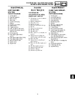
ELEC
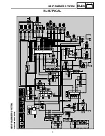
GRIP WARMER SYSTEM
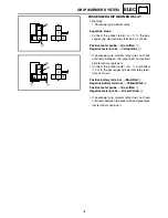
PASSENGER GRIP WARMER RELAY
1. Remove:
• Passenger grip warmer relay
Inspection steps:
• Connect the pocket tester (
Ω
×
1) to the pas-
senger grip warmer relay terminals as shown.
• If passenger grip warmer relay does not have
continuity between the green/red and yellow/
blue terminals, replace it.
• Connect the pocket tester (
Ω
×
1) and battery
(12 V) to the passenger grip warmer relay termi-
nals as shown.
• If passenger grip warmer relay does not have
continuity between the green/red and green/yel-
low terminals, replace it.
Positive tester probe
→
Green/Red
1
Negative tester probe
→
Yellow/Blue
2
Positive battery terminal
→
Blue/Red
3
Negative battery terminal
→
Yellow/Black
4
Positive tester probe
→
Green/Red
5
Negative tester probe
→
Green/Yellow
6
G
/
R
G
/
Y
L
/
R
Y
/
L
Y
/
B
1
2
G
/
R
G
/
Y
L
/
R
Y
/
L
Y
/
B
6
5
4
3
Содержание RST90GTY
Страница 12: ......
Страница 15: ...CABLE ROUTING 102 ...
Страница 19: ...ALLMÄN VÄGLEDNING FÖR ÅTDRAGNINGSMOMENT 101 DEFINITION AV ENHETER 101 KABELDRAGNING 102 ...
Страница 127: ...FI ...
Страница 183: ...FI ...
Страница 271: ...SPEC ...
Страница 272: ...102 SPEC CABLE ROUTING 8 9 0 A B C E F G C C D 1 2 3 4 5 5 6 7 A B A B ...
Страница 286: ...116 SPEC CABLE ROUTING G H I J E F 8 9 0 A B C D 1 2 3 4 5 6 7 K L M Y N O O P Q R S T U V W X A A ...
Страница 288: ...118 SPEC CABLE ROUTING G H I J E F 8 9 0 A B C D 1 2 3 4 5 6 7 K L M Y N O O P Q R S T U V W X A A ...
Страница 290: ...120 SPEC CABLE ROUTING E F G H I A B C D 1 2 3 4 5 8 9 0 6 7 J K K L M N C C B B A A D A A A A B B D C C ...
Страница 292: ...122 SPEC CABLE ROUTING E F G H I A B C D 1 2 3 4 5 8 9 0 6 7 J K K L M N C C B B A A D A A A A B B D C C ...
Страница 294: ......
Страница 295: ......

