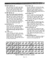
109. GROUP SUB IN (1 - 8)
These eight female XLR connectors apply signal
directly to the group mixing busses (ahead of the
Group Insert point and Group Master Faders).
They are used for “chaining” another mixing
console’s group outputs into this console, with this
console serving as the master for both consoles.
110. MTRX SUB IN (1 - 8)
These eight female XLR connectors apply signal
directly to the correspondingly numbered MTRX
SUB IN controls [28]. These inputs can be used to
apply effects return signals to individual matrix
channels, to apply remote signals to the matrix, or
to "Y" connect one or more aux send busses to the
matrix for in order to create additional groups.
MTRX SUB IN also may be used for “chaining”
another mixing console’s matrix outputs into this
console, with this console’s MTRX MASTERs
serving as the masters for both consoles.
111. AUX SUB IN (1 - 8)
These eight female XLR connectors apply signal
directly to the auxiliary mixing busses (ahead of
the Aux Insert point and Aux Master Level
controls). They are used for “chaining” another
mixing console’s aux send outputs into this console,
with this console serving as the master for both
consoles.
112. 2 TR IN 1 (L, R)
This pair of female XLR connectors make signal
available to the Monitor A and Monitor B sections,
where the signal can be selected and fed to
headphones or monitor speakers. The input is
nominally intended for return (playback) from a
two-track tape machine, although it can be used for
any stereo, line-level input.
113. 2 TR IN 2 (L, R)
This pair of female XLR connectors make signal
available to the Monitor A and Monitor B sections,
where the signal can be selected and fed to
headphones or monitor speakers. The input is
nominally intended for return (playback) from a
two-track tape machine, although it can be used for
any stereo, line-level input.
114. ST SUB IN (L, R)
This pair of female XLR connectors apply signal
directly to the stereo mixing busses (ahead of the
Stereo Insert point and Stereo Master Faders).
They are used for "chaining" another mixing
console’s stereo outputs into this console, with this
console serving as the master for both consoles.
115. CUE SUB IN (L, R)
This pair of female XLR connectors apply signal
directly to the stereo cue mixing bus (ahead of the
Monitor A Level control). They are used for
"chaining" another mixing console’s cue (or solo)
outputs into this console, with this console serving
as the master for both consoles.
116. AUX ST SUB IN 1 (L, R)
This pair of female XLR connectors apply signal
directly to auxiliary stereo mixing bus 1 (ahead of
the Aux Stereo Insert point and Aux Stereo Master
Level control). They are used for "chaining" another
mixing console’s aux stereo outputs into this
console, with this console serving as the master for
both consoles.
117. AUX ST SUB IN 2 (L, R)
This pair of female XLR connectors are identical to
the AUX ST SUB IN 1 connectors [116], except
they go to the #2 auxiliary stereo bus.
Figure 2-9. PM4000 Rear Panel: Sub In Connectors
Page 2-29
Содержание PM4000
Страница 1: ...PROFESSIONAL AUDIO MIXING CONSOLE PM4000 OPERATING MANUAL YAMAHA ...
Страница 2: ...PM4000 OPERATING MANUAL ...
Страница 7: ...Section 1 Introduction ...
Страница 11: ...Section 2 Brief Operating Instruction ...
Страница 47: ...Section 3 Specifications ...
Страница 51: ...Dimensional Drawings PM4000 Console all versions Page 3 4 ...
Страница 52: ...Page 3 5 ...
Страница 53: ...Page 3 6 PM4000 Console Rear Profiles ...
Страница 54: ...Module Block Diagrams See back of the manual for overall system block diagram Page 3 7 ...
Страница 55: ...Page 3 8 ...
Страница 56: ...Page 3 9 ...
Страница 57: ...Page 3 10 ...
Страница 58: ...Page 3 11 ...
Страница 59: ...Page 3 12 ...
Страница 60: ...Section 4 Installation Notes ...
Страница 72: ...Figure 4 13 Cables For Use With Balanced Sources Page 4 12 ...
Страница 79: ...SECTION 5 Gain Structure and Levels ...
Страница 82: ...Figure 5 1 Dynamic Range and Headroom in Sound Systems Page 5 3 ...
Страница 86: ...Section 6 Optional Functions ...
Страница 106: ...Section 7 Operating Notes and Hints ...
Страница 119: ...Section 8 Applications ...
Страница 124: ...Figure 8 3 System Diagram For 5 Independent Stereo Output Mixes via the Stereo Bus and the Mix Matrix Page 8 5 ...
Страница 127: ...Section 9 Maintenance ...
Страница 131: ......
Страница 132: ...YAMAHA VN02300 ...


