background image

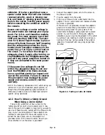
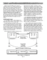
Figure 4-2. Testing a 2-wire AC Outlet and a

3-Prong to 2-Prong Adaptor

4.2.4 Improperly Wired AC Outlets:

Lifted Grounds

A "lifted ground" condition exists if the ground or

If you detect any voltage between the larger slot

(white wire) in an outlet and the ground-terminal

(round prong, green wire) when there is no load on that

line, you should contact a licensed electrician to check it

out and correct the situation.

green wire from the outlet’s safety ground is discon-

nected or missing. In older wiring, the heavy green wire

was sometimes omitted from internal wall wiring in

favor of letting the metal flex conduit or pipe suffice as

the ground path from the electrical service entrance.

This method of grounding is generally acceptable, as

long as the metal conduit in the wall is intact and all

the screws holding the joints together are secure.

However, a single loose screw in a conduit joint inside a

wall can remove the safety ground from the next outlet

box in the line, and from all the subsequent boxes on

that same line.

WARNING: In AC power wiring, black is

hot, and white is neutral-the opposite of

most audio signal wiring and speaker

wiring. It is safer to consider all AC wiring

as potentially lethal. It is possible some-

one miswired the system, or that a short

circuit has developed. Test the voltages

yourself, and be safe.

Page 4-3

4.2.5 Improperly Wired AC Outlets:

Lifted Neutral

If the neutral becomes lifted at a power outlet, it is

possible that items plugged into the outlet will be fed

the full 220 to 240 volts available from the power

service instead of the desired 110 to 120 volts.

Such outlets may operate, but the voltage can swing

from 0 volts to 220 or 240 volts AC (or whatever the

maximum voltage at the service entrance), creating a

shock hazard and possibly damaging your equipment.

Although the white wires (neutral) and

the green wires (ground) in the AC wiring

are technically at the same potential

(voltage), and should measure the same

potential using a voltmeter, the ground

prong connections at the outlets should be

connected to the grounding bar that was

driven into the earth as an additional

safety precaution in case something

should happen to the wires running from

the service entrance transformer to the

building or within the equipment itself. If

a short should occur within the equip-

ment, hopefully the electricity will find its

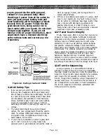
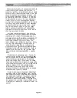
Figure 4-3. Schematic of an Outlet

With a Lifted Neutral

If the PW4000 is plugged into one socket of the two

outlets with lifted neutral, and a rack of signal process-

ing equipment or power amplifiers is plugged into the

other, fuses would probably blow upon turning on the

system, and some of the sound equipment could be

destroyed.

Содержание PM4000

Страница 1: ...PROFESSIONAL AUDIO MIXING CONSOLE PM4000 OPERATING MANUAL YAMAHA ...

Страница 2: ...PM4000 OPERATING MANUAL ...

Страница 3: ...arth symbol or coloured GREEN or GREEN AND YELLOW The wire which is coloured BLUE must be connected to the terminal which is marked with the letter N or coloured BLACK The wire which is coloured BROWN must be connected to the terminal which is marked with the letter L or coloured RED This applies only to products distributed by YAMAHA KEMBLE MUSIC U K LTD Professional audio mixing console Typ PM40...

Страница 4: ... shock hazard do not expose this appliance to rain or moisture There are eight groups or subgroups depending on your linguistic preference The group faders are known as Group Master Faders Their function is to control the level on the eight Group Mixing Busses The eight group busses are different and distinct from the eight Auxiliary Mixing Busses The Stereo Fader is actually a pair of closely spa...

Страница 5: ...edance Lines 4 15 4 5 Direct Boxes Page Sect Title 4 15 4 5 1 Passive Guitar Direct Box 4 17 4 5 2 Active Guitar Direct Box 4 17 4 6 Configuring Equipment Racks Section 5 Gain Structure and Levels 5 1 5 1 Standard Operating Levels 5 2 5 2 Dynamic Range and Headroom 5 2 5 2 1 What Is Dynamic Range 5 2 5 2 2 The Relationship Between Sound Levels and Signal Levels 5 2 5 2 3 A Discussion Of Headroom 5...

Страница 6: ...forcement 7 9 7 2 4 2 Using The Matrix Sub Inputs For Effects 7 9 7 2 4 3 Other Uses For The Matrix Sub Inputs 7 10 7 2 4 4 Use of the Matrix to Pre Mix Scenes 7 10 7 2 5 Understanding and Use of The Master Mute Function 7 12 7 2 6 Stereo Panning To the Eight Group Mixing Busses Page Sect Title Section 8 Applications 8 1 8 1 8 1 8 2 8 2 8 3 8 3 8 3 8 4 8 4 8 6 8 7 8 l General 8 1 1 Theatre 8 1 2 P...

Страница 7: ...Section 1 Introduction ...

Страница 8: ...s required While the console has ample headroom throughout it is always possible to incor rectly set controls For this reason the PM4000 is equipped with level detection at several stages Input LED meters and PEAK LEDs are provided The latter not only monitor the input preamp level they check for overboost in the EQ section too Metering can be front panel switched to pre or post fader actually pre...

Страница 9: ...eatrical scene changes and so forth If however it is imperative that a certain channel never be inadvertently muted or that muting temporarily be overrid den the input channel s MUTE SAFE switch can be engaged Muting can also be controlled remotely via a rear panel connec tor so automation here too is possible In addition to the master muting function the VCA master faders have mute switches which...

Страница 10: ... you a comprehensive view of signal levels in your system PM4000 electronic performance is everything you d expect from the people who developed the PM3000 It is even more advanced with lower noise levels than ever Wide headroom throughout exceptionally low distor tion and quiet controls are the hallmark of this top quality mixing console The specifications are honest and conservative The performa...

Страница 11: ...Section 2 Brief Operating Instruction ...

Страница 12: ... less signal to each bus than the level obtained with full left or right assignment so that the combined stereo signal across a given pair of busses adds up to constant power at all PAN pot positions 3 ST Stereo Figure 2 1a PM4000 Standard Input Module upper portion of module Section 2 Brief Operating Instructions 2 1 PM4000 Front Panel Features NOTE Features are numbered to correspond with the nu...

Страница 13: ...th or without the pad engaged Listen for noise and distortion though if the signal is noisy don t use the pad If there is a lot of distortion use the pad Front Bandwidth panel Q octave 3 0 0 5 1 4 1 0 center position 1 2 1 2 0 7 2 0 0 5 2 5 7 PEAK This red LED turns on to indicate when the signal present after the channel preamp is too high in level The LED triggers 3 dB below clipping and should ...

Страница 14: ...ilter from 20 Hz to 400 Hz The filter slope is 12 dB per octave Typical applications including cutting wind noise vocal P pops stage rumble and low frequency leakage from adjacent instruments You can use higher frequency settings to reduce leakage into mics that are primarily handling high frequency sources It is a good practice to use the filter to protect woofers from unnecessary over excursion ...

Страница 15: ... Aux Master LEVEL controls If you reset the Pre function for the sends of some busses or on some channels it is a good idea to attach a note to the console indicating how you have set it up CAUTION Any input module may be used as an auxiliary return If a module is used in this way DO NOT assign the return to the same auxiliary bus whose output is feeding the signal processor which is providing the...

Страница 16: ...nd the two pair of stereo aux mixing busses Engaging the switch does not necessarily mean the switch will be illuminated or that the channel will turn on muting logic may be dictating that the channel remain off When the channel is OFF the feed to the VU meter is also off although the signal may still be previewed with the CUE SOLO switch 26 Figure 2 1c PM4000 Standard Input Module lower portion o...

Страница 17: ...or Stereo L R by pressing the corresponding CUE switches In most cases once the individual output mixes have been estab lished the engineer will want to listen to the most important output mix during the perfor mance possibly the main house feed or the vocal group However should feedback occur or should any other condition require attention the PM4000 enables the engineer to instantly check any in...

Страница 18: ...ules actually perform the assignment and if desired you need not assign the modules s outputs as shipped from the factory For that matter you can assign stereo modules in any mainframe position to either the ST CH3 or ST CH4 bus by means of these on board selector switches Moreover if you do assign the output to ST CH3 or ST CH4 you may decide to cut internal jumpers and thereby defeat the module ...

Страница 19: ...fore it is a good practice to turn off the channel s phantom power unless it is actually in use NOTE The console s microphone power supply is not intended for A B powered microphones External sup plies may be used with these devices in which case the console s phantom power should be turned OFF on the appropriate channels The optional input transformers if installed do not affect phantom power ope...

Страница 20: ...aneously affecting the left and right sides of the channel 9 HIGH Peak Shelf This locking switch selects peaking type EQ switch out or shelving type EQ switch en gaged When the switch is engaged shelving mode the adjacent Q control is not operational Q This rotary control adjusts the Q the bandwidth of this section of the equalizer from a very narrow band to a very broad band with a center detent ...

Страница 21: ...fers from unnecessary over excursion due to the presence of unneeded low frequency or sub sonic components especially if a microphone is dropped or kicked Bypass the filter switch up only when you want very low frequencies as with an organ drum bass guitar and so forth 15 feature number 15 is not used in this mod ule 16 INSERT ON This locking switch activates the channel s INSERT IN jacks from whi...

Страница 22: ...s a single stereo Aux send with level and balance controls The outer PRE OFF POST stitch on the left hand control set determines whether the send is off derives signal before the fader and equalizer of after them just as with the individual aux sends This function affects both sides of the AUX ST 1 output whether used for stereo or dual mono sends The outer switch on the right hand control set det...

Страница 23: ...is on it overrides any combination of MASTER MUTE and channel MUTE switch settings and prevents the channel from being muted Engag ing this switch ensures the channel will always be on so long as the channel ON switch is also engaged 25 FADER This long throw fader sets the level applied to the 8 group mixing busses and the stereo bus It also affects any auxiliary feeds which are set to post fader ...

Страница 24: ... correspondingly numbered group mixing busses applied to the module s MTRX OUT There will only be signal available however if the correspondingly numbered master modules GROUP TO MTRX switch 41 is engaged The signal applied to the matrix mix is nominally derived post group master fader but an internal jumper switch in each master module permits this to be changed to a pre group master fader signal...

Страница 25: ...UT connector 36 INSERT Aux insert The aux send master circuit has an insert Out In patch point located just before its master level control The OUT jack is always active If this switch is engaged LED illuminated the IN jack becomes active Thus engaging the INSERT switch can insert a signal processor in the aux channel or it can substitute an external line level input instead of the mixed aux signa...

Страница 26: ...group signal is assigned to the matrix NOTE The signal derivation is preset by means of a switch within each of the master modules As shipped the group feed to the matrix comes after the Group Master Fader Moving the switch within each master module changes this to a pre Group Master Fader feed to the matrix Refer to Section 6 for more information on this optional preset switch function 42 GROUP M...

Страница 27: ...d amplifier in a given input module will be the sum of the voltages from that module s channel fader plus any assigned VCA Master faders The higher the voltage the greater the gain through the channel VCA gain structure is calculated so that when a VCA Master Fader is set so its NOMINAL LED is on then that Fader has no affect on any input channel levels The VCA Master faders should be set to NOMIN...

Страница 28: ...ont center position The lower control then serves as a master level control that simultaneously affects both sides of the Aux 1 stereo output With the switch engaged illuminated the upper control serves as a master level control for the mono signal feeding the Aux 1 Right output connector and the lower one as the master level control for the Aux 1 Left output connector 49 BAL LEVEL locking switch ...

Страница 29: ...tive If this switch is engaged LED illuminated the L R IN jacks become active Thus engaging the INSERT switch can insert a stereo signal processor or a pair of mono proces sors in the stereo master output or it can substi tute an external line level input instead of the mixed stereo signals NOTE The Stereo Sub In jacks apply signal to the aux mix ahead of the insert point so sub in program will be...

Страница 30: ... the bus The TB or OSC signal is mono and is assigned equally to the left and right sides of the stereo bus 64 TB OUT This locking switch turns the TB OUT connector on and off It affects only the feed to the VU meter and the output of the talkback system which appears at the TB OUT connector the output being derived from the TB input when the TALKBACK ON switch is pressed or otherwise from the osc...

Страница 31: ...hen the oscillator is set for 10K Hz switch 67 the sweep mode enables you to adjust the actual oscillator frequency between 2 kHz and 20 kHz 69 LEVEL OSC This rotary control adjusts the oscillator output level applied to the OSC OUT connector as well as any mixing busses to which the signal may be assigned This control does not affect the Talkback level 70 48V This switch turns phantom power on an...

Страница 32: ... its MUTE SAFE switch is engaged This rotary control adjusts the signal level after the talkback preamplifier thereby affecting the sensitivity of the TB input whether it is set for a mic or line source This control affects the TB level applied to any busses and to the TB OUT connector it does not affect the oscillator level 74 TALKBACK ON two way lever switch and LED indicator Pulling this switch...

Страница 33: ...Switches These six interlocking switches determine the signal available at the Monitor B output The first two switches select signals from rear panel connectors 2TR IN 1 two track tape input 1 and 2TR IN 2 two track tape input 2 ST CH 3 and ST CH4 select respectively any signals which have been derived from stereo input modules whose internal assign switches are set to the ST IN 3 or 4 MON buses T...

Страница 34: ...ese three groupings and they are divided into four stereo pairs see bus group selectors 85 below 85 1 2 3 4 5 6 7 8 Aux Group Mtrx bus group selectors Pressing one of these four switches selects the bus pair which the associated AUX GROUP or MTRX switch 84 will feed to the Monitor A output 86 LEVEL Monitor A level control This rotary control sets the level of the signal going to the Monitor A left...

Страница 35: ...that flashes if the console is in the SOLO mode This serves as an urgent warning that if any input CUE SOLO switch is depressed that all input channels will be muted except the soloed channel s CAUTION If the red SOLO LED is flash ing during a performance DO NOT press any input CUE SOLO switch Instead disengage the SOLO MODE switch 77 This will prevent program interruption when attempting to cue a...

Страница 36: ...e priority on meters so labeled as described below The meter bridge also has indicators to display power supply condition as well as a dimmer control for the lamp connectors on the rear of the bridge 93 PW MONITOR 48 12 19 19 Power supply indicators These five LEDs monitor the condition of the remote power supply The 19 19 12 and 48 LEDs should normally be on indicating the corresponding voltages ...

Страница 37: ...witching 98 AUX ST 1L MON A L AUX ST 1R MON A R meters and indicator These two meters normally monitor the corre spondingly labeled auxiliary 1 stereo left and right sides When the an input or bus CUE switch is engaged the meters display the Monitor A output signal which is the cue signal and the MON indicator above the meters turns on 99 AUX ST 2 L TB AUX ST 2 R OSC meters and indicator These two...

Страница 38: ...jacks serve as a patch point for the signal from the correspondingly numbered input channel Nominal output and input level is 4 dBu 1 23 V The OUT jack may be used as an auxiliary output to another console or as a direct output to a multitrack tape machine although a separate DIRECT OUT jack is provided for this purpose 103 It is most often likely to be used for sending the input channel signal to...

Страница 39: ...2 28 104 INPUT L INPUT R connectors These electronically balanced female XLR 3 connectors apply signal to the left and right sides of the correspondingly numbered input channel The nominal input level may vary from 70 dBu to 4 dBu depending on the settings of the channel input gain control and 30 dB pad switch Since stereo input GAIN 5S is a split control the sensitivity of the L and R input conne...

Страница 40: ...return playback from a two track tape machine although it can be used for any stereo line level input 113 2 TR IN 2 L R This pair of female XLR connectors make signal available to the Monitor A and Monitor B sections where the signal can be selected and fed to headphones or monitor speakers The input is nominally intended for return playback from a two track tape machine although it can be used fo...

Страница 41: ...switch in each bus 43 which can bypass the INSERT IN jack regardless of whether an external source is plugged in or not 119 MTRX INSERT 1 8 IN OUT These phone jacks serve as a patch point for the signal from the correspondingly numbered matrix mixing bus They function identically to the insert points for the group mixing bus 118 and are located in the mixed matrix signal path including sub in ahea...

Страница 42: ...n groups 1 through 4 and 5 through 8 is the same as that for the VCAs 125 Control is applied via the same multipin remote connector as the VCAs 129 127 PHANTOM MASTER 48V This recessed slide switch turns the console s 48 volt phantom power supply on and off When this is OFF no power will be supplied to any mic regardless of the channel s 48 V on off switch setting 4 128 FAN speed switch This switc...

Страница 43: ...T 1 8 These eight male XLR connectors output signal from the eight 11 1 matrix mixes after the MTRX MASTER controls and ON off switches They may be used for feeding mono or stereo tape recorders multiple zones of a sound system multiple sound systems or remotes depending upon the application In some instances these outputs can be used for effects sends or for monitors 132 AUX OUT 1 8 These eight m...

Страница 44: ... foldback stage monitors for auxiliary mono or stereo program feeds to remote locations and or tape recorders and so forth 137 AUX ST 2 OUT L R These two male XLRs are identical to the AUX ST 1 connectors but derive signal from the number 2 stereo aux mix 138 MONITOR OUTPUT A L R This pair of XLR connectors output the same Monitor A selected signal which appears at the PHONES output jacks 92 Howev...

Страница 45: ...9V outputs are operating Below that is a corresponding row of UNUSUAL LEDs one or more of which illuminates if the output is not within normal tolerance There is also a green POWER indicator that is illuminated when power is turned on a red THERMAL indicator that is illuminated when the power supply has overheated and automatically shut down and a digital indicator that displays the AC line voltag...

Страница 46: ...6 A Sub Fuse 3A NOTE Internal fuses in the PW4000 are also present but should not normally blow These are for service by qualified service personnel only 2 19V 3 FRAME GND 4 19V 5 19V 6 FRAME GND 7 FRAME GND 8 19V 9 19V 10 19V GND 11 19V GND 12 12V GND 13 19V 14 19V 16 19V GND 17 12V GND 18 12V GND 19 PM CAUTION 20 48V 21 48V GND 22 12V 23 12V 24 PW CAUTION 25 NC 26 NC 27 12V 146 Power Cord This p...

Страница 47: ...Section 3 Specifications ...

Страница 48: ...X ST OUT POST LVL 87 dB CH IN to AUX ST OUT PRE PAN 84 dB CH IN to CH DIRECT OUT 104 dB CH IN to MONITOR OUT GROUP to MONITOR 84 dB CH IN MONITOR OUT INPUT CUE 94 dB ST IN ST L R to GROUP OUT 91 dB ST IN L R to GROUP OUT 87 dB ST IN ST L R to AUX OUT mono PRE 90 dB ST IN L R to AUX OUT mono PRE 90 dB ST IN ST L R to AUX ST OUT stereo PRE LVL 87 dB ST IN L R to AUX ST OUT stereo PRE LVL 87 dB ST IN...

Страница 49: ...OUP 4 MTRX 4 AUX ST2R 13 GROUP 5 MTRX 5 MONITOR A L pre 14 GROUP 6 MTRX 6 MONITOR A R pre 15 GROUP 7 MTRX 7 TB 16 GROUP 8 MTRX 8 OSC Built into each VU meter the LED turns on when the pre line amp level reaches 3 dB below clipping Available at balanced inputs via 6 6 κΩ current limiting isolation resistors for powering condenser microphones may be turned ON or OFF via rear panel Phantom Master swi...

Страница 50: ...alanced with Tip signal high Ring signal low and Sleeve ground 3 In these specifications when dB represents a specific voltage 0 dB is referenced to 0 775 Vrms 4 Sensitivity is the lowest level that will produce an output of 4 dB 1 23 V or the nominal output level when the unit is set to maximum level OUTPUT CHARACTERISTICS Connection GROUP OUT 1 8 STEREO OUT L R MTRIX OUT 1 8 AUX OUT 1 8 AUX ST1 ...

Страница 51: ...Dimensional Drawings PM4000 Console all versions Page 3 4 ...

Страница 52: ...Page 3 5 ...

Страница 53: ...Page 3 6 PM4000 Console Rear Profiles ...

Страница 54: ...Module Block Diagrams See back of the manual for overall system block diagram Page 3 7 ...

Страница 55: ...Page 3 8 ...

Страница 56: ...Page 3 9 ...

Страница 57: ...Page 3 10 ...

Страница 58: ...Page 3 11 ...

Страница 59: ...Page 3 12 ...

Страница 60: ...Section 4 Installation Notes ...

Страница 61: ...les 4 2 Power Mains 4 2 1 Verify The Correct Mains Voltage PW4000 power supplies sold in the U S A and Canada are designed to operate with 110 to 120 volt 50 or 60 Hz AC power mains The General Export model operates on 220 to 230 volt 50 or 60 Hz AC mains The British model operates on 240V AC mains If you are traveling with this equipment be sure to test the power mains and to use the appropriate ...

Страница 62: ...and Canadian power systems al though the principles generally apply worldwide In other areas however be sure to check local codes for specific wiring standards 4 2 3 How To Obtain a Safety Ground When Using a 2 wire Outlet Two wire AC outlets do not have a hole for the safety ground prong of a 3 wire power cord A two wire to three wire AC adaptor is required if you want to use one of these two wir...

Страница 63: ... system or that a short circuit has developed Test the voltages yourself and be safe Page 4 3 4 2 5 Improperly Wired AC Outlets Lifted Neutral If the neutral becomes lifted at a power outlet it is possible that items plugged into the outlet will be fed the full 220 to 240 volts available from the power service instead of the desired 110 to 120 volts Such outlets may operate but the voltage can swi...

Страница 64: ...a venue don t plug in your equipment Any fault in the wiring of the AC outlet is potentially hazardous Rather than take a chance with damage to equipment and possibly lethal shock it is best to refuse to use a faulty outlet until it has been repaired by a licensed electrician Don t take unnecessary risks 4 2 7 Power Source Integrity Finally make every effort to assure that your source of power is ...

Страница 65: ...nces Signal Ground the reference point against which signal potentials in a specific piece of equip ment or group of components are expressed Earth Ground the local electrical potential of the earth In practice earth is the potential of the central rounded terminal in a U S standard three prong 120 volt outlet Earth is sometimes obtained from a metal cold water pipe though this practice has been c...

Страница 66: ...rienced audio engineers Sometimes in poorly designed sound equipment which sometimes includes expensive sound equipment ground loops occur inside the chassis even though the equipment has balanced inputs and outputs In this instance little can be done to get rid of the hum short of having a skilled audio engineer redesign the ground wiring inside It s better to avoid this kind of equipment It is a...

Страница 67: ...ipment racks It is almost impossible to implement in complex portable sound reinforcement systems Multiple point grounding is shown in Figure 4 7 This situation is common in systems that use unbal anced equipment having the chassis connected to signal ground It has the advantage of being very simple in practice but it is not very reliable particularly if the connection configuration of the system ...

Страница 68: ...ined within an electro static shield which drains to earth Equipment Rack 2 Connect signal ground within each separate sub system to earth at one point only 3 Provide maximum isolation in connections between subsystems by using transformer coupled floating balanced connections 4 3 4 Balanced Lines and Ground Lift Switches By using balanced signal lines between two pieces of sound equipment you can...

Страница 69: ...nd the chassis of the particular device Ground lift switches are usually found on direct boxes which are used when an electric musical instrument is to be plugged directly into a console whose inputs are not designed to accommodate direct connection of such instruments a direct box also includes a transformer and or isolation amplifier as discussed in Section 4 5 One of the best ways to exclude no...

Страница 70: ...and audio lines by as wide a distance as is practical and where they must cross try to lay them out to cross at as close to a right angle as possible The balanced line is a three wire system where two signal wires carry an equal amount of potential or voltage with respect to the shield ground wire but of opposite electrical polarity from each other The shield ground in a balanced line does not car...

Страница 71: ...Cables For Use With Unbalanced Sources NOTE regarding Figure 4 12 For microphone cables conect the shield to pin 1 at both ends of the XLR cable For line level signal cables cut the shield as illustrated Page 4 11 ...

Страница 72: ...Figure 4 13 Cables For Use With Balanced Sources Page 4 12 ...

Страница 73: ...eoretically perfect balanced system only the desired signal gets through the differential amplifier or trans former Figure 4 14 Noise Rejection In a Balanced Line NOTE regarding Figure 4 14 There are significant differences in the way various balanced outputs are designed When a balanced output is driving an unbal anced input it is best to use a dual conductor shielded cable connecting the shield ...

Страница 74: ...o pay the price carry the weight or incur the slight performance penalty that comes with the trans formers NOTE There are other ways to achieve isolation The most common means is with a wireless radio mic One can digitize the audio signal and transmit it by means of modulated light in fiber optics but this is much more expensive than using a transformer with no great performance advantage One can ...

Страница 75: ... of each of these types of direct boxes originally designed by the late Deane Jensen While these designs are believed to work well with the PM4000 their inclusion in this manual does not represent an endorsement by Yamaha of the specific products mentioned The specified transformers are available from Jensen Transformers Inc 10735 Burbank Blvd North Hollywood CA 91601 Phone 213 876 0059 4 5 1 Pass...

Страница 76: ... output etc 5 1 metal film resistors such as Roederstein resista MK 2 are recommended for their low noise and audio quality although the nearest 5 1 4 watt carbon film values shown in parentheses will work with reduced accuracy 6 Optional 2 5 linear taper potentiometer allows continuously variable attenuation between 10 dB and 20 dB Conductive plastic is recommended but carbon will work OK 7 Pin 2...

Страница 77: ... consid ered 4 6 Configuring Equipment Racks The great majority of audio equipment manufactur ers make provision for their electronic products to be mounted in EIA standard 19 inch wide equipment racks The equipment may be only 17 to 18 inches in width or even less The rack ears that mount to the rack rails extend to 19 inches Panel heights for rack mounting equipment are standardized on multiples...

Страница 78: ...ntegral power distribution ground fault indica tion and a well stocked spare fuse compartment are among the extra touches that are usually provided Equipment that may generate strong electromagnetic fields power amps with large transformers should be separated from equipment that has high gain micro phone and phono cartridge preamplifiers or cassette decks The hallmark of a professional rack is th...

Страница 79: ...SECTION 5 Gain Structure and Levels ...

Страница 80: ...f the professional equip ment has a higher impedance input the output voltage of the hi fi equipment may still be inadequate The typical result is too low levels and too high distortion This can damage loudspeakers due to the high fre quency energy content of the clipped waveform and it can damage the hi fi equipment due to overloading of its output circuitry There are exceptions but one should be...

Страница 81: ...n 20 dB is the headroom not 20 dBu Provided the 250 watt rated power amplifier is operated just below its clipping level at maximum peaks of 250 watts and at nominal levels of 2 5 watts then it also operates with 20 dB of head room 20 dB above nominal 100 times the power 5 2 4 What Happens When The Program Source Has Wider Dynamics Than The Sound Equipment If another mixing console were equipped w...

Страница 82: ...Figure 5 1 Dynamic Range and Headroom in Sound Systems Page 5 3 ...

Страница 83: ...m level as required to achieve a given headroom value using the amplifier s input attenuators Input attenuators should be set so that maximum program levels from the source equipment won t drive the amplifiers to clipping or at least won t do it very often This keeps overall system noise as low as possible Page 5 4 5 2 6 How To Select a Headroom Value and Adjust Levels Accordingly Recall that head...

Страница 84: ... and the equalizer input The nominal signal level at the input to the equalizer should now be 2 dBu 616 mV which can be checked with a voltmeter 5 Assume that the maximum rated output level of the equalizer in this example is 18 dBu 6 16 volts Adjust the master level control on the equalizer so that its output level is 20 dB below the rated maximum or 2 dBu 616 mV If the equalizer has no built in ...

Страница 85: ...ive device such as a passive filter set graphic equalizer or low level crossover network Such devices will attenuate some of the signal often 6 dB or more Here the extra output capability of the console offsets the loss of the passive signal processor so that adequate signal can be delivered to the power amplifiers tape machine inputs etc Consider those instances where the PM4000 outputs are conne...

Страница 86: ...Section 6 Optional Functions ...

Страница 87: ...present inside the power supply and the AC line cord and console umbilical cord should be disconnected prior to opening the console WARNING We at Yamaha additionally caution you never to open the console and remove or install a module for the pur pose of inspection replacement or chang ing the preset switches unless the power has first been turned off If a module is removed or installed with power...

Страница 88: ...up gently on a control knob and you will feel the two module connectors that join the connectors on the bottom of the console release Then carefully lift the module out of the console 6 1C 5 Installation of a module should be done by reversing the order of this procedure Work slowly to make sure that edge connectors mate properly NOTE If you are moving a module to a different loca tion in the main...

Страница 89: ... the Direct Out to be Pre EQ and Fader actually pre VCA move the switch to the appropriate position as illustrated As shipped the direct out point comes ahead of the Channel ON switch and is thus not affected by the Master Mute function By changing internal jumpers you can alter the Direct Out point to be Post ON switch also illustrated below in Figure 6 2 Figure 6 2 Internal Switch Positions For ...

Страница 90: ...ng is desirable On the other hand suppose that one aux mix is used for a pre fader effects send In this case it may be desirable to apply channel EQ to the send The POST position would provide EQ but would also cause the channel fader to affect the send which is not desirable To solve the problem the switch for that aux send can be reset so that the PRE position remains pre fader but This is usefu...

Страница 91: ...of the channel fader actually just ahead of the fader controlled VCA However an internal jumper in each mono input module enables this function to be altered VCA to be more exact until the METER PRE switch is set to Pre mode then it will be pre fader The channel s CUE output has left and right components but both are derived from the same monaural signalThe switch positions are illustrated below i...

Страница 92: ...ght cue Pre mode then it will be pre fader The channel s CUE busses from a point which is derived just ahead of the output has true stereo left and right components channel fader actually just ahead of the fader con derived from the discrete stereo input The switch trolled VCA However an internal jumper in each positions are illustrated below in Figure 6 5 stereo input module enables this function...

Страница 93: ... meter s MT PRE switch function to be altered As shipped when the channel is set so that the meter is in show the level after the Fader but before the channel ON switch This is useful for checking and adjusting the level even though the channel output is muted via a Master Mute function or the channel on off switch Figure 6 6 Internal Jumper Positions For MT PRE switch Post function Being Post Fad...

Страница 94: ...t points to be altered separately ize equalize the return from a signal processor In this case the In Out points can be switched to come before As shipped the console is set so that the Insert In Out points come after the channel equalizer This is useful the channel equalizer Move the jumpers to the appro priate position as illustrated Figure 6 7 Internal Jumper Positions For Pre EQ and Post EQ In...

Страница 95: ...ule that aux send can be reset so that the PRE position permit each of the eight mono auxiliary sends and to be remains pre fader but is taken after the EQ This is the altered Two more switches perform the same function same as the corresponding function on the mono input for the two stereo aux sends As shipped the console is wired so that if the front panel aux PRE OFF POST module Figure 6 8 Inte...

Страница 96: ...put module left input path and the even numbered Aux Sends changes the signal source for the Aux Sends 1 through 8 derive signal from the channel s right input path See without regard to pre or post status As shipped these Figure 6 9 Aux Sends each carry a mono combination of the left Figure 6 9 Internal Switch Position For Stereo Input Module Aux Send 1 8 Mono Combine or Stereo Paired Signal Sour...

Страница 97: ...mono L R com A slide switch in each stereo input module changes bined signal i e while the level applied to the L R the signal source for the two stereo aux sends without aux busses can be varied the signal itself is the same regard to pre or post status As shipped the two Stereo See Figure 6 10 Figure 6 10 Internal Switch Position For Stereo Input Module ST Aux Send 1 2 Mono combine or Stereo Pai...

Страница 98: ... module and Stereo In 4 modules However the stereo module Locate the switch Fig 6 11 and set it as shown so numbers are arbitrarily designated stereo modules can that a given module either does not contribute anything be located in just about any mainframe input module to these monitor busses or so it contributes to ST IN3 location and more than one can contribute to the ST or ST IN4 bus IN3 or ST...

Страница 99: ... polarity of the left input with respect to the right input you must reset a switch on the module s circuit board Once this switch is reset to the alternate position then engaging the front panel Ø switch reverses polarity of the channel s left input only See Figure 6 12 Figure 6 12 Internal Switch Position For Al tering the Stereo Input Module Phase ø Switch Function for Combined L R Phase Change...

Страница 100: ...tput to the eight group busses by moving the header two pin clip to the position which does not complete the circuit to the output another pair of jumpers kill the output to the stereo bus another three pair of jumpers kill the post fader pre EQ and post EQ feeds to the aux busses These jumpers are identified in Figure 6 13 shatter eardrums and shred loudspeakers Careful operation can avoid this p...

Страница 101: ...uts can be adjusted with another Group Master Fader etc Suppose however that you plan to feed a six mono mixes or a total of four stereo mixes A greater number of mixes can be obtained by selecting the alternate pre Group Master Fader switch positions In that case you can assign the Group Outputs to the stereo bus via the GROUP TO ST switch 40 and the adjacent PAN pot 41 the Group Master Faders wi...

Страница 102: ...d its signal after the Stereo Master fader 58 so that adjust ments in the stereo output also affect the feed to the matrix The internal switch can be repositioned so that the matrix is fed pre Stereo Master fader In this way the stereo output can be used for one feed and it can be remixed in the matrix to create other stereo feeds Figure 6 15 Internal Switch Positions For Pre and Post Stereo Maste...

Страница 103: ... transformer onto the included fitting with the nut as shown in Figure 6 16B 4 Being careful with the wiring unfasten Angle H of the module by removing the two small flat head screws and the two small bind screws 5 From the inside of Angle H insert the two small M3 screws provided and attach the transformer fitting Figure 6 16C 6 Reset Angle H to its original position 7 Pass all the wiring through...

Страница 104: ...ative which drives the VCA to 10 dB of gain If several VCA faders are set above nominal and assigned to a channel the maximum negative voltage that will be applied to the VCA is 1 2 VDC a DC limiter circuit prevents any more negative voltage from being passed and turns on the VCA MAX LED This corresponds to 24 dB of gain At minimum VCA fader setting the output is 10 VDC corresponding to over 100 d...

Страница 105: ...OR 10 kohm W HU07712 F 1 METALIZED FILM RESISTOR 12 kohm W HU07713 2 F METALIZED FILM RESISTOR 13 kohm W HK05715 1 J CARBON RESISTOR 15 kohm W HK05733 1 J CARBON RESISTOR 33 kohm W IG06920 3 IC AMP MJM2041DD HT56009 1 B SEMI FIXEDVR TRIMMER 50 kohm IF00004 2 DIODE 1S1555 IF00214 1 ZENER DIODE RD5 6ED2 VA25610 1 B SLIDER VR FADER 10 kohm Table 6 1 Parts List for Making Remote VCA Control Circuit Fi...

Страница 106: ...Section 7 Operating Notes and Hints ...

Страница 107: ...distance between these two lines at any point along the horizontal signal flow scale depicts the available headroom It is important that wide headroom be available throughout a console not just at the input and output otherwise multiple signals applied to the busses may add together such that the mixed level approaches clipping even though the individual feeds to the mix are within their acceptabl...

Страница 108: ...happen to be assigned to a given VCA Master you can pull down that VCA Master which in turn will reduce the signals applied to the group bus This will leave the Group Master Fader at the desired nominal position will preserve the desired balance between input channels and will keep the bus level from being too hot Finally release the Group CUE switch 7 1 4 Establishing The Correct Group Master Set...

Страница 109: ... the bus Masters may be used for minor touch up level adjustments If the level is much too high on a given bus do not pull down its Master more than a few dB instead lower the Faders or Level controls for all signals which contribute to that bus 7 1 8 How VCA Control Affects Gain Structure Use of the VCA Master fader can complicate the gain structure considerably It is important to set up the inpu...

Страница 110: ...lifier in a conventional console configuration The PM4000 channel Fader is a variable resistor but it does not have audio flowing through it Instead it adjusts a DC voltage output from 0 volts at nominal position to 0 5 volts at maximum gain to 10 volts at infinite attenuation position The DC output voltage from the channel Fader is applied to the channel s VCA control input The VCA is a special a...

Страница 111: ... the VCA Masters while other channels can be assigned to different Group Master Faders and the Group Masters in turn can be assigned to stereo using this approach one has the equivalent of 16 groups mixed to stereo What cannot be done with a Group Master Fader 42 that can be done with a VCA Master 47 is control ling the post fader AUX SEND levels from groups of input channels While it s true that ...

Страница 112: ...ected at random in this illustration The Group 1 Master Fader controls the Post input Fader signals from all of these input channels Similarly the AUX 4 Master Send Level Control adjusts the 4 AUX Output from all of these input channels In this way a single effects unit can process the grouped signals if it is placed in the Group Insert or AUX Master Insert IN OUT point Figure 7 2 Signal Processin...

Страница 113: ...ols can be set as needed for the various input sources When playing back the multitrack tape the PAD switches and GAIN controls need not be readjusted instead simply engage the channel INSERT ON switches 16 to select the tape returns The same concept applies where the console is used for multiple stage setups as in subsequent scenes in a theatrical presentation or different sets for a live musical...

Страница 114: ...The Mix Matrix is Located on the Top portion of Master Modules 1 8 Figure 7 3 Front Panel View and Block Diagram of PM4000 Mix Matrix Page 7 8 ...

Страница 115: ...escribed in Sections 6 12 and 6 13 then the Group and Stereo Master Faders will not affect the matrix mix levels In this case the matrix can be used in much the way to create the necessary mono or stereo house feeds while the group and or stereo outputs can be mixed independently to feed a multitrack tape recorder Whereas the signals applied to tape are generally recorded at a uniformly hot level ...

Страница 116: ...he desired balance of Groups 1 8 and of the Stereo mix blending these ten sources into two MTRX MASTER controlled outputs that are ideally suited to the first scene You can use the next two mix matrix channels to create a differently bal anced mix for the next scene and so forth The only trick if you think about it is that each pair of matrix outputs must still feed the same pair of power amplifie...

Страница 117: ...led with one MUTE MASTER while other input channels may continue feeding that group output Thus the mute function is distinctly different than the Group or Stereo output ON off switches Things can become more complex when an input channel is assigned to more than one MUTE MASTER switch In this case the mere act of releasing one MUTE MASTER may not turn on the channel if the channel is still being ...

Страница 118: ...in stereo with many input channels assigned directly to the stereo bus via the ST switch 3 In this situation however the drums are being mixed in stereo and must be compressed as a group One does not want the drum compression to affect the other channels There fore the drum input channels can be assigned to a pair of odd and even numbered group busses and the stereo mix created with the input PAN ...

Страница 119: ...Section 8 Applications ...

Страница 120: ...ired for each of the areas If a simultaneous recording is needed the matrix can be set to mix signals from ahead of the group and stereo master faders so the group and stereo outputs can be used for independent multitrack and two track tape recording mixes Control room outputs make it possible to monitor the console outputs while working in an isolated booth they even carry the cue signal so that ...

Страница 121: ...and defects surgically removed using the four band parametric equalizers on each input channel as well as the sweep frequency high pass filters that go as high as 400 Hz Insert in out jacks on every bus and input channel make it possible to patch in whatever signal processing is desired Insert On switches on the input channels let you switch the signal processor in or out of the circuit with the t...

Страница 122: ...ted to prevent potential feedback from inadvertent output to input assignment looping Eight VCA Masters provide another means to deal with groups of inputs use the conventional groups where it is necessary to insert a signal processor in the group signal path or use the VCAs where it is necessary to affect all the outputs from a given input channel Scene changes can be handled with the VCA groups ...

Страница 123: ...that the Group to Mtrx feeds are derived pre Group Master Fader see Section 6 12 The eight Group Master Faders 42 may then be assigned to the Stereo Master Faders 58 by engaging the Group to ST switches 40 In this case the Group Master Faders function as subgroup controls for the overall mixed output controlled by the Stereo Master Faders These outputs can be used for a stereo program or for two m...

Страница 124: ...Figure 8 3 System Diagram For 5 Independent Stereo Output Mixes via the Stereo Bus and the Mix Matrix Page 8 5 ...

Страница 125: ... those channels VCA assign switches 22 are engaged typically just one switch per module The correspondingly numbered VCA Master Faders 47 then exercise control over subgroups of input channels which are assigned directly to the Stereo Master Fader The eight VCA Master Faders plus the eight Group Master Faders thus control 16 different subgroups all of which are mixed into the same stereo or dual m...

Страница 126: ...n be accommodated since some scenes may require two or more VCA Master Faders 47 to be brought up whereas other scenes may require just one of those VCA Masters or may require different settings of the same VCA Masters In any event just eight faders need be monitored and reset not 24 to 48 each time there is a scene change As an adjunct to this technique the channel MUTE switches 23 and MUTE MASTE...

Страница 127: ...Section 9 Maintenance ...

Страница 128: ...rable noise When a component is to be cleaned use a very small amount of an appropriate cleaner solvent or pure isopropyl alcohol Try to get it on the element and immediately work the pot or fader several times all the way between stops In general cleaning pots and faders is not a trivial task Some have carbon elements some have conductive plastic elements and others have cermet elements What clea...

Страница 129: ... engaged Certain input channels or groups of The affected input channel s have VCA Disengage VCA assign switch on the channel channels cannot be heard at Group assign switches engaged and the VCA affected or raise the VCA Master Fader to a Stereo Post Fader Aux sends or Matrix Master Fader to which the channel s is higher setting outputs assigned is set to minimum level down The affected input cha...

Страница 130: ...er Avenue Scarborough Ontario M1S 3R1 Canada Yamaha Europa G m b H Siemensstr 22 34 2084 Rellingen b Hamburg Germany Yamaha Kemble Music U K Ltd Sherbourne Drive Tilbrook Milton Keynes MK7 8BL England Yamaha Scandinavia AB Box 300 53 400 43 Göteborg Sweden Yamaha Musique France S A Parc d Activités de Paris Est Rue Ambroise Croizat 77183 Croissy Beaubourg France Yamaha Hazen Electronica Musical S ...

Страница 131: ......

Страница 132: ...YAMAHA VN02300 ...

Отзывы: