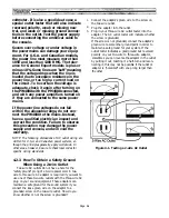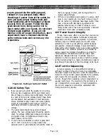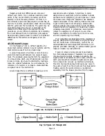
which is ideal. Each winding, each Faraday shield, and
the transformer chassis shield should have separate
leads.
Figure 4-15. Passive Musical Instrument Direct Box (D.I. Box) Schematic Diagram
Notes Regarding Figure 4-15:
1. C1 is a high quality, non-polar aluminum electro-
lytic, such as Roederstein type EKU. Voltage rating
should be 25 V or higher. If non-polar cap is not
available, use two 47µF, 25V polarized electrolytics
in series. Because of their high distortion, tantalum
capacitors are not recommended for C1.
2. C2 is an optional high quality (polypropylene or
polycarbonate) film capacitor used together with C1
to improve the sonic quality of the input capacitor.
3. C3 is a high quality (polystyrene or polypropylene)
film capacitor. Adjust the value for the desired high-
frequency rolloff (filter works only with pad in
circuit).
4. Pad circuitry must always be used when the source
is line or speaker level (synthesizer, guitar amp
output, etc.).
5. 1% metal film resistors such as Roederstein
(resista) MK-2 are recommended for their low noise
and audio quality, although the nearest 5%, 1/4 watt
carbon film (values shown in parentheses) will work
with reduced accuracy.
6. Optional 2.5
linear taper potentiometer allows
continuously variable attenuation between -10 dB
and -20 dB. Conductive plastic is recommended,
but carbon will work OK.
7. Pin 2 of the microphone-level output connector is
“Hi,” Pin 3 is “Lo,” in order to comply with I.E.C.
standards. This is compatible with Neumann, AKG,
Beyer, Shure, Sennheiser, Crown, EV, and Shoeps
microphones, all of which are Pin 2 “Hot.”
8. 3 resistor across transformer secondary should
be installed when the direct box is used with inputs
having greater than 2 actual termination
impedance (for example, a standard Yamaha
PM2800M input). It is OK to leave the resistor in
circuit with 1 inputs, although better results will
be obtained if the resistor is omitted in this case.
9. Parts kit DB-E-PK-1 containing all resistors and
capacitors needed to build above circuit available
from Jensen Transformers, N. Hollywood, CA for
nominal fee.
Page 4-16
Содержание PM4000
Страница 1: ...PROFESSIONAL AUDIO MIXING CONSOLE PM4000 OPERATING MANUAL YAMAHA ...
Страница 2: ...PM4000 OPERATING MANUAL ...
Страница 7: ...Section 1 Introduction ...
Страница 11: ...Section 2 Brief Operating Instruction ...
Страница 47: ...Section 3 Specifications ...
Страница 51: ...Dimensional Drawings PM4000 Console all versions Page 3 4 ...
Страница 52: ...Page 3 5 ...
Страница 53: ...Page 3 6 PM4000 Console Rear Profiles ...
Страница 54: ...Module Block Diagrams See back of the manual for overall system block diagram Page 3 7 ...
Страница 55: ...Page 3 8 ...
Страница 56: ...Page 3 9 ...
Страница 57: ...Page 3 10 ...
Страница 58: ...Page 3 11 ...
Страница 59: ...Page 3 12 ...
Страница 60: ...Section 4 Installation Notes ...
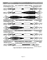
Страница 72: ...Figure 4 13 Cables For Use With Balanced Sources Page 4 12 ...
Страница 79: ...SECTION 5 Gain Structure and Levels ...
Страница 82: ...Figure 5 1 Dynamic Range and Headroom in Sound Systems Page 5 3 ...
Страница 86: ...Section 6 Optional Functions ...
Страница 106: ...Section 7 Operating Notes and Hints ...
Страница 119: ...Section 8 Applications ...
Страница 124: ...Figure 8 3 System Diagram For 5 Independent Stereo Output Mixes via the Stereo Bus and the Mix Matrix Page 8 5 ...
Страница 127: ...Section 9 Maintenance ...
Страница 131: ......
Страница 132: ...YAMAHA VN02300 ...

