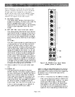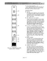
2 . 1 . 4 T h e S t e r e o M a s t e r M o d u l e
This module controls the output of the stereo bus and
the two aux stereo busses.
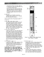
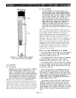
Figure 2-4a. PM4000 Stereo Master Module
(upper portion of module)
51. CUE (Aux 1 Stereo cue)
Pressing this switch part-way down causes
momentary contact; pressing it further locks it
down. When the CUE switch is illuminated, the
aux 1 master cue mix signal (post insert point,
pre master control) replaces any other signal in
the Cue output and the Phones output unless an
input CUE switch is engaged. (Bus cue signals
are overriden by input cue.) The aux 1 stereo cue
signal is stereo.
Page 2-17
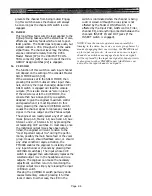
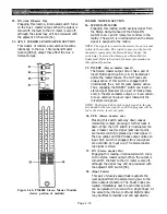
AUX 2 STEREO SEND MASTER SECTION
48. BAL/LEVEL R and LEVEL/LEVEL L (rotary
controls)
This pair of rotary controls’ functions depends on
the setting of the BAL/LEVEL switch [49].
With the switch disengaged (not illuminated), the
upper control serves as a balance control, in-
creasing the level in the left in the left output and
decreasing the right output level of the Aux 1
stereo output as the control is rotated counter-
clockwise from center, or vice-versa as it is
rotated clockwise front center position. The lower
control then serves as a master level control that
simultaneously affects both sides of the Aux 1
stereo output
With the switch engaged (illuminated), the upper
control serves as a master level control for the
mono signal feeding the Aux 1 Right output
connector, and the lower one as the master level
control for the Aux 1 Left output connector.
49. BAL/LEVEL (locking switch)
This switch determines whether the pair of
rotary controls above and below it serve as
separate level controls for the Aux 1 left and right
outputs (switch engaged and illuminated) or as
balance and level controls for the Aux 1 outputs
(switch up, LED off).
50. INSERT (Aux 1 Stereo insert)
The Aux 1 Stereo output circuit has a pair of
insert Out/In patch points (L & R) located just
before its master level and balance controls. The
OUT jacks are always active. If this switch is
engaged (LED illuminated), the L & R IN jacks
become active. Thus, engaging the INSERT
switch can insert a stereo signal processor (or a
pair of mono processors) in the aux channel, or it
can substitute an external line-level input in-
stead of the mixed aux signals.
NOTE: The Aux Stereo Sub In jacks apply signal to the
aux mix ahead of the insert point, so aux sub-in program
will be fed to the aux insert out jacks.
Содержание PM4000
Страница 1: ...PROFESSIONAL AUDIO MIXING CONSOLE PM4000 OPERATING MANUAL YAMAHA ...
Страница 2: ...PM4000 OPERATING MANUAL ...
Страница 7: ...Section 1 Introduction ...
Страница 11: ...Section 2 Brief Operating Instruction ...
Страница 47: ...Section 3 Specifications ...
Страница 51: ...Dimensional Drawings PM4000 Console all versions Page 3 4 ...
Страница 52: ...Page 3 5 ...
Страница 53: ...Page 3 6 PM4000 Console Rear Profiles ...
Страница 54: ...Module Block Diagrams See back of the manual for overall system block diagram Page 3 7 ...
Страница 55: ...Page 3 8 ...
Страница 56: ...Page 3 9 ...
Страница 57: ...Page 3 10 ...
Страница 58: ...Page 3 11 ...
Страница 59: ...Page 3 12 ...
Страница 60: ...Section 4 Installation Notes ...
Страница 72: ...Figure 4 13 Cables For Use With Balanced Sources Page 4 12 ...
Страница 79: ...SECTION 5 Gain Structure and Levels ...
Страница 82: ...Figure 5 1 Dynamic Range and Headroom in Sound Systems Page 5 3 ...
Страница 86: ...Section 6 Optional Functions ...
Страница 106: ...Section 7 Operating Notes and Hints ...
Страница 119: ...Section 8 Applications ...
Страница 124: ...Figure 8 3 System Diagram For 5 Independent Stereo Output Mixes via the Stereo Bus and the Mix Matrix Page 8 5 ...
Страница 127: ...Section 9 Maintenance ...
Страница 131: ......
Страница 132: ...YAMAHA VN02300 ...


