4.5 Direct Boxes
The so-called “direct box” is a device one uses to
overcome several of the problems that occur when
connecting electric guitars and some electronic key-
boards to a mixing console. By using a transformer, the
direct box provides important grounding isolation to
protect a guitarist from inadvertent electrical shock in
the event of a failure in the guitar amplifier or other
equipment’s power supply. The second thing the direct
box does is to match the impedance of the instrument to
that of the console input. Electric guitar pickups are
very high impedance devices, and they are easily
overloaded by anything less than a 100,000 ohm input
termination. Connection of an electric guitar to the
typical 600 to 10,000 ohm console input will cause a
noticeable loss in signal level and degradation of high
frequencies. While the impedance and level mismatch is
less of a problem with electronic keyboards, such
instruments often have unbalanced outputs which are,
nonetheless, susceptible to hum and noise where long
cables are required to reach the mixing console. To
avoid these problems, a direct box can be connected
near the instrument, and the output of the direct box
then feeds the console.
NOTE: If a preamplifier head is used, a direct box is not
necessary since the head provides a balanced, isolated
output to a console.
One further application of the direct box is to isolate
and pad the speaker-level output of an instrument
amplifier so that signal can be fed to the console input.
Normally, one would not connect a speaker-level signal
to a console input. However, the reverb, tremolo,
distortion, EQ, and other characteristics of many
instrument amps are an integral part of the
instrument’s sound. If the amp head does not provide a
line-level output for a console, then a suitably designed
direct box can “tap” the speaker output for feed to the
console. Even where a line level output is provided,
sometimes the coloration of the signal at the speaker
output (due to intentional clipping of the power amp
section of the guitar amplifier, and back EMF from the
speaker) is desired, and can only be obtained at the
speaker terminals.
There are two main variations of the direct box: the
passive version, with only a transformer, and the active
version, which employs a powered circuit in addition to
the transformer and thus provides minimum pickup
loading while boosting low level signals from the guitar
pickup for maximum noise immunity. We present
information here for constructing one of each of these
types of direct boxes, originally designed by the late
Deane Jensen. While these designs are believed to work
well with the PM4000, their inclusion in this manual
does not represent an endorsement by Yamaha of the
specific products mentioned. The specified transformers
are available from Jensen Transformers, Inc., 10735
Burbank Blvd., North Hollywood, CA 91601. Phone
(213) 876-0059.
4.5.1 Passive Guitar Direct Box
This direct box is not a commercial product, though
it can be assembled by any competent technician. It can
be used in three ways:
1. At the output of a standard electric guitar, without
an amplifier (pad switch open, ground switch
closed),
2. At the output of a standard guitar with a guitar
amplifier also connected (pad switch open, ground
switch open or closed),
3. At the output of a guitar or instrument amplifier
(pad switched in, ground switch open or closed).
The filter switch, which only works when the pad
switch is closed, simulates the high frequency roll off of
the typical guitar amp speaker. Since clipping distortion
in a guitar amp creates high frequency harmonics, the
filter switch, by attenuating the high frequency re-
sponse, also cuts distortion. The filter and pad, however,
are optional and may be omitted if the box is to be used
strictly between the guitar pickup and the console.
The transformer was designed specifically for use in
a guitar direct box. When connected to a typical electric
guitar pickup, and an XLR channel input on a PM4000,
the transformer reflects the optimum load impedance to
both the guitar pickup and the mic preamp input. This
preserves optimum frequency response and transient
response. The transformer has two Faraday shields to
prevent grounding and shielding problems that could
cause hum in the PM4000 or the guitar/instrument
amplifier. Place the ground switch in whichever position
works best.
Assembly can be accomplished in a small metal box.
Keep the phone jack electrically isolated from the
chassis of the box. During operation, keep the chassis of
the box away from the chassis of any guitar/instrument
amp or any other grounded object. If you decide to use a
transformer other than the Jensen model JT-DB-E, it
should have similar characteristics: an impedance
ratio of 20K ohms (primary) to 150 ohms (secondary),
dual Faraday shields, very low capacitance primary
winding, and full audio spectrum frequency response.
Note that, as used, this produces an approximate 133K
ohm “load” for the guitar when connected to a nominal
1K ohm console input (the approximate actual load
impedance of most mic inputs). The PM4000’s electroni-
cally balanced XLR inputs are rated at 3K ohms, so the
load on the guitar pickup would be nearly 500K ohms,
Page 4-15
Содержание PM4000
Страница 1: ...PROFESSIONAL AUDIO MIXING CONSOLE PM4000 OPERATING MANUAL YAMAHA ...
Страница 2: ...PM4000 OPERATING MANUAL ...
Страница 7: ...Section 1 Introduction ...
Страница 11: ...Section 2 Brief Operating Instruction ...
Страница 47: ...Section 3 Specifications ...
Страница 51: ...Dimensional Drawings PM4000 Console all versions Page 3 4 ...
Страница 52: ...Page 3 5 ...
Страница 53: ...Page 3 6 PM4000 Console Rear Profiles ...
Страница 54: ...Module Block Diagrams See back of the manual for overall system block diagram Page 3 7 ...
Страница 55: ...Page 3 8 ...
Страница 56: ...Page 3 9 ...
Страница 57: ...Page 3 10 ...
Страница 58: ...Page 3 11 ...
Страница 59: ...Page 3 12 ...
Страница 60: ...Section 4 Installation Notes ...
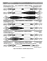
Страница 72: ...Figure 4 13 Cables For Use With Balanced Sources Page 4 12 ...
Страница 79: ...SECTION 5 Gain Structure and Levels ...
Страница 82: ...Figure 5 1 Dynamic Range and Headroom in Sound Systems Page 5 3 ...
Страница 86: ...Section 6 Optional Functions ...
Страница 106: ...Section 7 Operating Notes and Hints ...
Страница 119: ...Section 8 Applications ...
Страница 124: ...Figure 8 3 System Diagram For 5 Independent Stereo Output Mixes via the Stereo Bus and the Mix Matrix Page 8 5 ...
Страница 127: ...Section 9 Maintenance ...
Страница 131: ......
Страница 132: ...YAMAHA VN02300 ...

