The PM4000 is fitted with only two types of audio
connectors: 3-pin XLRs, both male and female, and 3-
circuit (tip/ring/sleeve)
¼”
phone jacks (also known as
stereo phone jacks, although their function is sometimes
to carry a balanced mono signal rather than a stereo
signal).
4.4.1 Types of Cable To Use
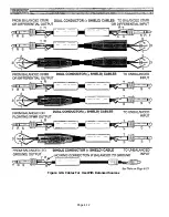
2-conductor (twisted pair) shielded cable is best for
all XLR connections. Belden 8412, Canare L4E6S, or an
equivalent are excellent choices due to their heavy duty
construction, multiple strands that avoid breakage,
good flexibility, and good shielding. Such cables are
suitable for all portable applications, and for micro-
phones. For permanent installation or for cables con-
fined to portable racks or cases, a lighter duty cable
such as Belden 8451, Canare L-2E5AT or an equivalent
are suitable. “Snake” type multi-core cables containing
multiple shielded pairs must be handled very carefully
because the leads tend to be fragile, and a broken
conductor cannot be repaired. If you are using a “snake,”
allow at least one or two spare channels that can be used in
case of breakage in one of the channels in use.
For the same reasons that mic and line level cables
should be separated, so, too, should speaker cables (the
cables run between the power amp output and the
speakers) be separated from mic or line level cables. If
speaker cables cross other audio cables, they should do
so at right angles. If they must be run along the same
path, they should not be bundled tightly.
4.4.3 Balanced versus Unbalanced Wiring
In a general sense, there are two types of signal
transmission systems for low to medium level audio
signals: the balanced line, and the unbalanced line.
Either type can be used with high or low impedance
circuits; the impedance of a line bears no necessary
relationship to its being balanced or not.
The unbalanced line is a “two-wire” system where
the shield (ground) acts as one signal-carrying wire, and
the center (hot) wire enclosed within that shield is the
other signal-carrying wire.
4.4.2 Cable Layout
Never run AC power lines in the same conduit, or
even closely bundled, with audio cables. At the very
least, hum be induced from the relatively high
voltage AC circuits into the lower voltage audio circuits.
At worst, a fork lift or other object rolling or dropped
across the cables could cut through insulation, shunt
the AC into the audio cable, and instantly destroy the
audio equipment. Instead, separate AC and audio lines
by as wide a distance as is practical, and where they
must cross, try to lay them out to cross at as close to a
right angle as possible.
The balanced line is a three-wire system where two
signal wires carry an equal amount of potential or
voltage with respect to the shield (ground) wire, but of
opposite electrical polarity from each other. The shield
(ground) in a balanced line does not carry any audio
signal, and is intended strictly as a “drain” for spurious
noise current that may be induced in the cable from
external sources.
The shield in balanced and unbalanced cables is
typically a shell made of fine, braided wires, although
some cables have “served” (wrapped) shields or foil
shields instead.
Similarly, avoid closely bundling the line-level
outputs from the PM4000 with any mic-level inputs to
the console. Specifically, avoid using a single mutli-core
“snake” cable for running mic lines from the stage and
power amp feeds up to the stage. The close proximity of
such cables promotes inductive and/or capacitive
coupling of signals. If the stronger output signal from
the console "leaks" into the lower-level mic or line
feeding a console input, and that weaker signal is
amplified within the console, a feedback loop can be
established. This will not always be manifest as audible
“howling,” but instead may be manifest as very high
frequency (ultrasonic) oscillation that indirectly causes
distortion of the signal and that can lead to premature
component failure. The best solution is to widely
separate mic input cables from line-level output cables
or, if not practical, to at least bundle them loosely.
Balanced wiring is more expensive to implement
than unbalanced wiring. It is often used, however,
because it offers useful advantages, especially in
portable sound systems. There is nothing inherently
“better” or more “professional” about balanced wiring;
the application dictates whether one system or the other
is appropriate.
Unbalanced wiring works best when high-quality
cable is used, the cable extends over relatively short
distances, and one leg of the AC power system feeds all
the equipment. Unbalanced wiring is often used for
radio and TV signal transmission, computer data
transmission, and laboratory test equipment.
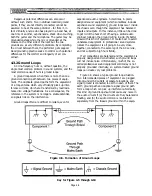
Balanced wiring helps eliminate some types of
externally-generated noise. The two wires of the “bal-
anced” cable carry the same signal, but each wire is
opposite in signal polarity to the other. In a balanced
input, both of the signal-carrying wires have the same
potential difference with respect to ground (they are
“balanced” with respect to ground), and the input is
Page 4-10
Содержание PM4000
Страница 1: ...PROFESSIONAL AUDIO MIXING CONSOLE PM4000 OPERATING MANUAL YAMAHA ...
Страница 2: ...PM4000 OPERATING MANUAL ...
Страница 7: ...Section 1 Introduction ...
Страница 11: ...Section 2 Brief Operating Instruction ...
Страница 47: ...Section 3 Specifications ...
Страница 51: ...Dimensional Drawings PM4000 Console all versions Page 3 4 ...
Страница 52: ...Page 3 5 ...
Страница 53: ...Page 3 6 PM4000 Console Rear Profiles ...
Страница 54: ...Module Block Diagrams See back of the manual for overall system block diagram Page 3 7 ...
Страница 55: ...Page 3 8 ...
Страница 56: ...Page 3 9 ...
Страница 57: ...Page 3 10 ...
Страница 58: ...Page 3 11 ...
Страница 59: ...Page 3 12 ...
Страница 60: ...Section 4 Installation Notes ...
Страница 72: ...Figure 4 13 Cables For Use With Balanced Sources Page 4 12 ...
Страница 79: ...SECTION 5 Gain Structure and Levels ...
Страница 82: ...Figure 5 1 Dynamic Range and Headroom in Sound Systems Page 5 3 ...
Страница 86: ...Section 6 Optional Functions ...
Страница 106: ...Section 7 Operating Notes and Hints ...
Страница 119: ...Section 8 Applications ...
Страница 124: ...Figure 8 3 System Diagram For 5 Independent Stereo Output Mixes via the Stereo Bus and the Mix Matrix Page 8 5 ...
Страница 127: ...Section 9 Maintenance ...
Страница 131: ......
Страница 132: ...YAMAHA VN02300 ...

