2.1.7 The Meter Bridge
The PM4000 is equipped with 2 jumbo and 12 or 16
large, illuminated VU meters, depending on the size of
the mainframe. Each meter has true VU ballistics to
indicate approximate loudness, plus a red "PEAK" LED
which responds to instantaneous levels that are beyond
the scale of the meter. The PEAK LED turns on 3 dB
below the clipping point. Assuming the meter is moni-
toring an output with +24 dBm maximum output
capability, the PEAK LED will turn on when the
instantaneous level r21 dBm. Since the stan-
dard VU meter scale goes only to +3 VU (which corre-
sponds roughly to +7 dBm with a steady-state signal),
the PEAK LED turns on when the level is about 7 dB
above maximum meter scale. Bear in mind, however,
that a brief transient that may cause the PEAK LED to
flash on may be too fast for the meter needle to respond.
It is not unusual with plucked or percussive instru-
ments, for example, for the peak level to be 20 to 30 dB
above the average level.
Most of the meters are switchable so they can
monitor two or three possible signal sources. When one
of the METER SELect switches [75] on the TB module
is engaged, an LED in the switch turns on to visually
confirm the signal being monitored. CUE and TB/OSC
signals automatically take priority on meters so labeled,
as described below.
The meter bridge also has indicators to display
power supply condition, as well as a dimmer control for
the lamp connectors on the rear of the bridge.
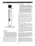
93. PW MONITOR, +48, +12, +19, -19 (Power
supply indicators)
These five LEDs monitor the condition of the
remote power supply. The -19, +19, +12 and +48
LEDs should normally be on, indicating the
corresponding voltages are being delivered to the
console. If there is a fault and one of the voltages
is low or dead, the PW CAUTION indicator will
flash to warn of a problem.
94. LAMP DIMMER
This rotary, dimmer turns the rear-panel lamp
sockets off, or on to a variable intensity from low
to high brightness. The console is shipped with
standard incandescent lamps in the LittLites, but
the hoods and power supply are designed so they
can accommodate the higher intensity quartz
lamps.
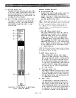
95. I (Group/Matrix/Aux meters and indicators)
These four meters (24 and 32 channel main-
frames) or eight meters (40 and 48 channel
mainframes) monitor the correspondingly num-
bered busses. These busses may be the group
output (GRP), the matrix output (MTRX) or the
auxiliary output (AUX) depending on the setting
of the METER SEL I switch on the TB module
[75]. The GRP, MTRX or AUX indicator above the
meters is illuminated to designate the output
levels on display.
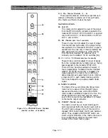
Figure 2-7a. PM4000 Meter Bridge for 24 or 32 Channel Mainframes
Figure 2-7b. PM4000 Meter Bridge for 40 or 48 Channel Mainframes
Page 2-25
Содержание PM4000
Страница 1: ...PROFESSIONAL AUDIO MIXING CONSOLE PM4000 OPERATING MANUAL YAMAHA ...
Страница 2: ...PM4000 OPERATING MANUAL ...
Страница 7: ...Section 1 Introduction ...
Страница 11: ...Section 2 Brief Operating Instruction ...
Страница 47: ...Section 3 Specifications ...
Страница 51: ...Dimensional Drawings PM4000 Console all versions Page 3 4 ...
Страница 52: ...Page 3 5 ...
Страница 53: ...Page 3 6 PM4000 Console Rear Profiles ...
Страница 54: ...Module Block Diagrams See back of the manual for overall system block diagram Page 3 7 ...
Страница 55: ...Page 3 8 ...
Страница 56: ...Page 3 9 ...
Страница 57: ...Page 3 10 ...
Страница 58: ...Page 3 11 ...
Страница 59: ...Page 3 12 ...
Страница 60: ...Section 4 Installation Notes ...
Страница 72: ...Figure 4 13 Cables For Use With Balanced Sources Page 4 12 ...
Страница 79: ...SECTION 5 Gain Structure and Levels ...
Страница 82: ...Figure 5 1 Dynamic Range and Headroom in Sound Systems Page 5 3 ...
Страница 86: ...Section 6 Optional Functions ...
Страница 106: ...Section 7 Operating Notes and Hints ...
Страница 119: ...Section 8 Applications ...
Страница 124: ...Figure 8 3 System Diagram For 5 Independent Stereo Output Mixes via the Stereo Bus and the Mix Matrix Page 8 5 ...
Страница 127: ...Section 9 Maintenance ...
Страница 131: ......
Страница 132: ...YAMAHA VN02300 ...


