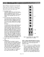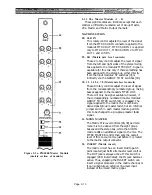
2.1.2. The Stereo Input Module
The PM4000 comes with at least four stereo input
modules, located in near the master section. More of
these stereo modules can be ordered in lieu of the
monaural input modules. Their position in the main-
frame is completely interchangeable with the standard
input modules (see Section 6 for details).
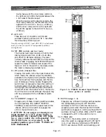
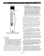
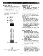
1S. 1 2 3 4 5 6 7 8 (ASSIGN switches)
These locking switches assign the channel output
to group mixing busses 1 through 8. The signal is
assigned as follows: the left input signal is routed
to the odd-numbered busses, and the right input
signal to the even-numbered busses. An LED
indicator in each switch turns on when the signal
is assigned to the bus. The relative level assigned
to any adjacent pair of odd and even busses
depends upon the use of the BAL/PAN switch and
control [2S].
NOTE: The stereo input modules in mainframe positions
#3 and #4 have stereo outputs that are permanently
assigned to the ST CH3 and ST CH4 busses. These
busses are routed only to the monitor module, and
permit direct monitoring of these stereo modules. Inter-
nal switches in these stereo modules actually perform the
assignment, and, if desired, you need not assign the
modules’s outputs as shipped from the factory. For that
matter, you can assign stereo modules in any mainframe
position to either the ST CH3 or ST CH4 bus by means
of these on-board selector switches. Moreover, if you do
assign the output to ST CH3 or ST CH4, you may decide
to cut internal jumpers and thereby defeat the module’s
output to any of the Group busses. If you do this, the
Group Assign switches [1S] will have no function,
although BAL/PAN [2S] will affect the feed to the ST
CH3 or ST CH4 bus. Refer to the Optional Functions in
Section 6 of this manual for details.
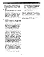
2S. BAL/PAN (pushbutton switch)
BAL/PAN (rotary control)
ST-L-R-L+R (concentric rotary
signal selector switch)
The locking BAL/PAN switch determines whether
the inner rotary control has any effect on the
signal or not. When the switch is engaged, the
control serves to either balance the stereo signal
between adjacent pairs of group mixing busses or
to pan the mono signal between these pairs of
busses.
The ST-L-R-L+R switch, which is concentric
with the balance/pan control, determines the
Figure 2-2a. PM4000 Stereo Input Module
nature of the signal being fed to the group and
(upper portion of module)
stereo output busses. In ST position, the left
Page 2-7
Содержание PM4000
Страница 1: ...PROFESSIONAL AUDIO MIXING CONSOLE PM4000 OPERATING MANUAL YAMAHA ...
Страница 2: ...PM4000 OPERATING MANUAL ...
Страница 7: ...Section 1 Introduction ...
Страница 11: ...Section 2 Brief Operating Instruction ...
Страница 47: ...Section 3 Specifications ...
Страница 51: ...Dimensional Drawings PM4000 Console all versions Page 3 4 ...
Страница 52: ...Page 3 5 ...
Страница 53: ...Page 3 6 PM4000 Console Rear Profiles ...
Страница 54: ...Module Block Diagrams See back of the manual for overall system block diagram Page 3 7 ...
Страница 55: ...Page 3 8 ...
Страница 56: ...Page 3 9 ...
Страница 57: ...Page 3 10 ...
Страница 58: ...Page 3 11 ...
Страница 59: ...Page 3 12 ...
Страница 60: ...Section 4 Installation Notes ...
Страница 72: ...Figure 4 13 Cables For Use With Balanced Sources Page 4 12 ...
Страница 79: ...SECTION 5 Gain Structure and Levels ...
Страница 82: ...Figure 5 1 Dynamic Range and Headroom in Sound Systems Page 5 3 ...
Страница 86: ...Section 6 Optional Functions ...
Страница 106: ...Section 7 Operating Notes and Hints ...
Страница 119: ...Section 8 Applications ...
Страница 124: ...Figure 8 3 System Diagram For 5 Independent Stereo Output Mixes via the Stereo Bus and the Mix Matrix Page 8 5 ...
Страница 127: ...Section 9 Maintenance ...
Страница 131: ......
Страница 132: ...YAMAHA VN02300 ...


