134. TB OUT
This male XLR connector outputs signal from the
talkback circuit when the TB OUT switch [64] is
on. If that switch is OFF, this output is muted.
Assuming the TB OUT switch is on, this output is
derived from the talkback input XLR when the
TALKBACK switch [74] is engaged. Otherwise the
TB OUT is derived from the console’s oscillator/
noise generator.
The TB OUT may be fed to the IFB (Interruptible
Foldback) program input of an intercom system in
order that the console operator can talk into the
intercom system. In some cases, it can be applied to
an auxiliary program audio input or some other
input on a standard intercom system. It also may
be fed to a monitor console’s input channel (which
is monitored via CUE) or COMM input to enable
the PM4000 operator to communicate with the
other console’s operator.
135. OSC OUT
This male XLR connector outputs signal from the
console’s oscillator/noise generator when the OSC
OUT switch [65] is on. In order to actually obtain
any output signal, however, the oscillator must be
switched on [67], and the OSC LEVEL control [69]
must be turned up.
136. AUX ST 1 OUT (L, R)
These two male XLR connectors output signal from
the stereo 1 auxiliary mixing bus, just after the
AUX ST 1 Master level controls [53]. They may be
used for echo/effects sends, for stage foldback (stage
monitors), for auxiliary mono or stereo program
feeds to remote locations and/or tape recorders, and
so forth.
137. AUX ST 2 OUT (L, R)
These two male XLRs are identical to the AUX ST
1 connectors, but derive signal from the number 2
stereo aux mix.
138. MONITOR OUTPUT A (L, R)
This pair of XLR connectors output the same
Monitor A selected signal which appears at the
PHONES output jacks [92]. However, the
MONITOR A OUT will be muted when the
Talkback function is activated, whereas the phones
output remains unmuted. If any CUE switch is
activated, then cue signal replaces the selected
Monitor A signal in these outputs. These
connectors are useful for driving control room
monitor amps and speakers for the console
operator, or a headphone distribution system (with
external power amp).
139. MONITOR OUTPUT B (L, R)
This pair of XLR connectors output the Monitor B
selected signal. The MONITOR B OUT will be
muted when the Talkback function is activated, but
are unaffected by the CUE function. These
connectors are useful for driving studio or stage
monitor amps and speakers, or a headphone
distribution system (with external power amp).
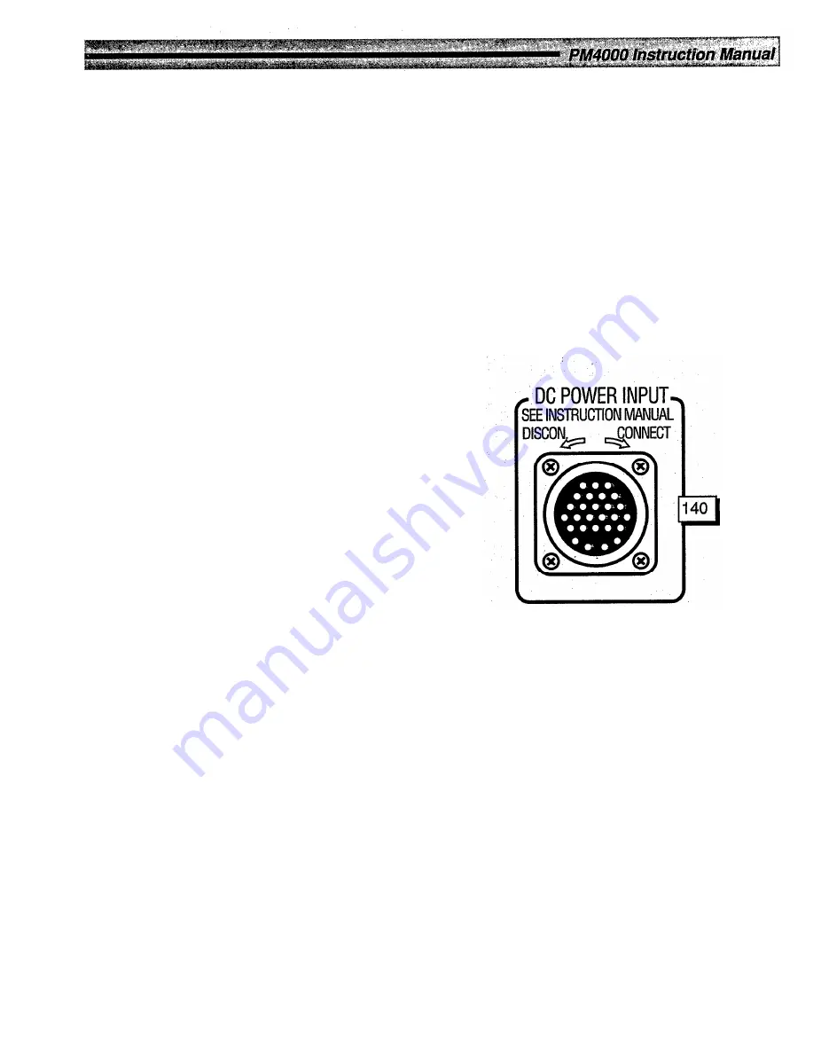
140. DC POWER INPUT
This multi-pin, locking connector accepts a special
umbilical cable from the console’s external power
supply (Model PW4000). The cable should be
carefully mated, making sure the locking ring is
securely hand tightened to avoid inadvertent
disconnection.
Figure 2-15. PM4000 Rear Panel: DC Power
Input Connector (see Fig 2-17 for Pin ID)
Page 2-33
Содержание PM4000
Страница 1: ...PROFESSIONAL AUDIO MIXING CONSOLE PM4000 OPERATING MANUAL YAMAHA ...
Страница 2: ...PM4000 OPERATING MANUAL ...
Страница 7: ...Section 1 Introduction ...
Страница 11: ...Section 2 Brief Operating Instruction ...
Страница 47: ...Section 3 Specifications ...
Страница 51: ...Dimensional Drawings PM4000 Console all versions Page 3 4 ...
Страница 52: ...Page 3 5 ...
Страница 53: ...Page 3 6 PM4000 Console Rear Profiles ...
Страница 54: ...Module Block Diagrams See back of the manual for overall system block diagram Page 3 7 ...
Страница 55: ...Page 3 8 ...
Страница 56: ...Page 3 9 ...
Страница 57: ...Page 3 10 ...
Страница 58: ...Page 3 11 ...
Страница 59: ...Page 3 12 ...
Страница 60: ...Section 4 Installation Notes ...
Страница 72: ...Figure 4 13 Cables For Use With Balanced Sources Page 4 12 ...
Страница 79: ...SECTION 5 Gain Structure and Levels ...
Страница 82: ...Figure 5 1 Dynamic Range and Headroom in Sound Systems Page 5 3 ...
Страница 86: ...Section 6 Optional Functions ...
Страница 106: ...Section 7 Operating Notes and Hints ...
Страница 119: ...Section 8 Applications ...
Страница 124: ...Figure 8 3 System Diagram For 5 Independent Stereo Output Mixes via the Stereo Bus and the Mix Matrix Page 8 5 ...
Страница 127: ...Section 9 Maintenance ...
Страница 131: ......
Страница 132: ...YAMAHA VN02300 ...


