XVIVO Perfusion System (XPS
TM
) Instructions for Use
-
1
P/N: 9182
0189 Revision Q
XVIVO PERFUSION SYSTEM (XPS
™)
SOFTWARE ver. 5.2
INSTRUCTIONS FOR USE
Ref: 19030 (US) and 19040 (CE)
Serial Numbers:
Страница 1: ...XVIVO Perfusion System XPSTM Instructions for Use 1 P N 9182 0189 Revision Q XVIVO PERFUSION SYSTEM XPS SOFTWARE ver 5 2 INSTRUCTIONS FOR USE Ref 19030 US and 19040 CE Serial Numbers XPS0101 ...
Страница 2: ... 3 Flow bubble sensor Technical Data English 100812 4 Hamilton C3 Operator s Manual 624446 03 Software version 2 0 x 2017 05 12 5 Hico Variotherm 550 Instructions for Use REF 542801 Rev 2 08 05 Manufacturer XVIVO Perfusion AB Box 53015 SE 400 14 Göteborg Sweden Visitors deliveries Mässans gata 10 SE 412 51 Göteborg Sweden Telephone 46 31 788 21 50 Distributed in the US by XVIVO Inc 3666 S Inca St ...
Страница 3: ...e labels and packaging Symbol Definition Power on off switch Manufacturer Date of manufacture Consult operator s manual Refer to the operator s manual for complete infor mation Indicates the degree of protection against electric shock according to IEC 60601 1 Class II devices have double or reinforced insulation as they have no provision for protective grounding C3 Ventilator only Canadian Standar...
Страница 4: ...7 UPS 29 CHAPTER 3 Lung Preparation 30 3 1 Lung Preservation 30 3 2 Protective Maintenance 30 3 3 Lung Cannulation 31 3 3 1 Ideal Lung Cannulation 31 3 3 2 Left Atrial LA Cannulation 32 3 3 3 Pulmonary Artery PA Cannulation 33 3 3 4 Intubation 34 3 3 5 Single Lung Cannulation 35 3 3 6 Back Table Flush 36 3 3 7 Pressure Sensors 37 3 3 8 Zero Pressure Sensors 38 3 3 9 Prime Lung Retrograde Flow 39 3...
Страница 5: ...1 4 5 4 Shutdown and Cleaning 62 CHAPTER 5 Notifications 63 5 1 Connections Date Time 64 5 2 XPSTM Software 65 72 CHAPTER 6 Equipment Alerts 73 6 1 Heater Cooler 74 6 2 CardioHelp XVIVO Alert Panels 75 6 2 1 CardioHelp XVIVO Medium priority 76 77 6 2 2 CardioHelp XVIVO Low priority 78 80 6 3 C3 Ventilator Alert Panels 81 6 3 1 C3 Ventilator 82 83 CHAPTER 7 Equipment Alarms 84 7 1 Heater Cooler 85 ...
Страница 6: ...aphics Window 98 8 7 2 Dynamic Lung 98 8 7 3 Dynamic Lung Compliance Graphics 99 8 7 4 Dynamic Loop Display 99 8 8 Monitored Parameters 100 101 Smart Sequencing 8 9 Smart Sequencing Table 102 103 EVENTS Page 8 10 History and Trend Logs Viewing and Downloading Files 104 8 11 Trend Log Data 105 106 CHAPTER 9 APPENDIX 2 Cleaning Maintenance 107 9 1 CardioHelp XVIVO 108 9 1 1 Cleaning 108 9 1 2 Mainte...
Страница 7: ...GM Sensors Technical Specifications 127 10 5 1 Technical Data pH Sensor 127 10 5 2 Technical Data PO2 Sensor 127 10 6 XVIVO Perfusion Cart System Technical Specs 128 10 6 1 Product Classification 128 10 6 2 Physical Characteristics 128 10 6 3 Environmental Requirements 128 10 6 4 Pneumatic Specifications 128 10 6 5 Electrical Specifications 129 10 6 6 Control Settings 129 10 6 7 Monitored Paramete...
Страница 8: ...igned to simulate the colloid osmotic pressure COP and crystalloid osmotic properties of human plasma to permit safe continuous ex vivo lung perfusion at normothermia for up to 6 hours without the development of either tissue edema or de hydration i e the COP and osmotic pres sure of the solution were chosen to maintain optimal water balance between the cellular and the intra and extra vascular sp...
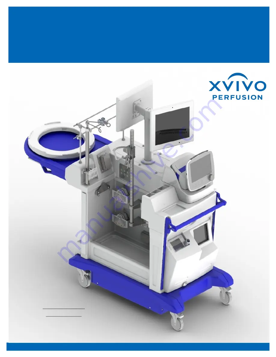
Страница 9: ...86 for deoxygenation membrane X Ray shelf Barcode Scanner Weight Sensor 1 2 XPSTM Cart Overview Intended Use The XVIVO Perfusion System XPS is indicated for use in flushing and temporary continuous normothermic machine perfusion of initially unacceptable excised donor lungs during which time the ex vivo function of the lungs can be reas sessed for transplantation US The XVIVO Perfusion System XPS ...
Страница 10: ...vated flow monitoring which triggers an alarm or intervention as necessary Warning Excessive electromagnetic interference can occur and interfere with the flow measurement of the flow bubble sensor This can result in incorrect measurements which cause incorrect value displays alarms flow regulation and interventions Warning Peristaltic pump heads can cause injury if touched while in operation with...
Страница 11: ... have been associated with rare allergic reactions However no such reactions have been reported with either of these substances when used for ex vivo lung preservation NOTE The XPSTM has been tested and found to comply with the limits for a Class A device pursuant to CISPR 11 and Part 18 of the FCC Rules These limits are designed to provide reasonable protection against harmful interference in a c...
Страница 12: ...DISPOSABLES In addition to the hardware cart the XPSTM includes the following single use disposable products designed for ex vivo lung perfusion XVIVO Organ ChamberTM to aseptically hold the lungs during the procedure XVIVO Disposable Lung Kit Fluid Level Sensor Pressure Sensor Line Disposable Pressure Transducer XVIVO Lung Cannula Kit Limb o Breathing Circuit Ventilator Flow Sensor Bacterial Vira...
Страница 13: ...s steel bar clips NOTE Clips can be autoclaved or drape can be clipped by perfu sionist from non sterile side Open the XVIVO Organ Cham ber outer box Remove the Chamber and open the plastic wrap by tearing along the blue dotted line that reads TEAR TO OPEN beginning at notch on either end Remove the Chamber from the poly bag and prepare to pass it off aseptically to the gowned scrub tech nurse Car...
Страница 14: ...e ex vivo lung The following components are part of the pack Quadrox iR centrifugal pump head oxygenation membrane heat exchanger Temperature probe 2 In line perfusate gas sensor 2 Leukocyte filter Flow probe Perfusion Loop Pulmonary artery cannula and pressure line Left atrial cannula and pressure line XVIVO Organ Chamber Hardshell reservoir Level sensor NOTE s 3 7 8 9 11 are pack aged separately...
Страница 15: ...lue wrapped drain bag section to the sterile side of the cart Sterilely connect the drain bag connector to the XVIVO Organ Chamber s drain port Pass drain bag back over to the non sterile wet area to attach to wall hooks Pass the perfusion loop section from 4 above quick connect ends through the sterile drape opening to the non sterile wet area Snap perfusion loop hoses into open tube clamps on ba...
Страница 16: ...EEN SolutionTM bottle holder as shown Feed the long STEEN Solu tionTM tubing piece through the closest peristaltic pump track and center tubing across middle of pump head Check to make sure tubing is centered between small black channels on both ends NOTE Safety guards not shown are installed over each peristaltic pump motor Carefully close pump head by moving lever all the way to the right Check ...
Страница 17: ...onTM recycle tubing which is a 24 inch piece of tubing connected to the drain bag with a red tape stripe Connect the open end of the recycle tubing to a reservoir inlet port and feed the STEEN Solu tionTM recycle tubing through the third pump head in the direction shown NOTE Tubing must be inserted from the RIGHT side entry to the LEFT side exit centered across peristaltic pump heads carefully fit...
Страница 18: ...le SensorTM Open sensor package NOTE Keep packaging label to enter calibration data into XPS Software in a later step Aseptically connect sensor to disposable tubing set using quick connects Sensor will only con nect in the correct orientation Insert sensor into housing as shown Repeat for second sensor ...
Страница 19: ...nnects to which port on oxygenator NOTE Water will leak out of Hansen connectors if they are not seated correctly Make sure they snap tightly onto heat exchange ports of oxygenator Set initial temperature of heater cooler unit to 23o C by using touch keypad If temperature is 35o C simultaneously press the temperature release key and the down arrow to achieve desired temperature setting Ensure ther...
Страница 20: ...ed into the wall outlet Note wall outlet should be equipped with back up power Turn toggle switch to the up position to initiate XPS system battery backup and press the UPS button Start CardioHelp and HCU by pressing power buttons for each Set HCU to 23 degrees Start Touchscreen monitor power button is located on the back of the monitor and Ven tilator by pressing power but tons for each 2 3 Power...
Страница 21: ...g normothermic ex vivo lung assessment The control panel includes the following areas Touch screen Panel Battery power LED AC DC power supply LED Safety Button Zero Flow Mode LED button Unlock LED button On Off LED button Control knob The main Home screen on the Touch display includes the follow ing areas Status bar Parameter display Toolbar Tab bar Power supply status 2 4 STEEN SOLUTIONTM PRIMING...
Страница 22: ...r bubbles throughout the main tube set Inject the following additives into the reservoir Methylprednisolone 500mg Broad spectrum antibiotic 500mg Heparin range 3000U 10 000 U where 10 000 U is the recommended value NOTE It is recommended to keep the pump control mode set to rpm instead of lpm to take advantage of the built in safety of a centrifugal pump that backs down delivered pressure in re sp...
Страница 23: ...g arrow toward the lung and snap to lock LEVEL Affix disposable level sensor pad to hard shell reservoir with the arrow pointing to the right and bottom edge of sensor lined up near 50ml mark NOTE The bottom edge of the sensor indicates the point at which the centrifugal pump will stop should the fluid level drop below the sensor Connect the level sensor to the sensor pad NOTE If fluid level shoul...
Страница 24: ...sor Clamp the perfusion tubing upstream of the flow sensor Touch the zero calibration symbol A message will ask Is the tube clamped before and after the flow sensor Confirm that it is by touching the confirm symbol Release the clamps in the re verse order upstream and then downstream NOTE If pump RPM is high 1000 but the flow rate is dis played as 0 check for kinks or obstructions in tubing lines ...
Страница 25: ...he flow sensor tub ing to the appropriately colored ports Connect venous mix gas line Connect high pressure oxygen line to port From the ventilator touch screen select the Preop check tab Select each calibration test one at a time by pressing on the buttons to the left in the following order Tightness Flow Sensor O2 cell typically performed during annual service only Follow the on screen instructi...
Страница 26: ... to include with the perfusion record After data is entered click the Submit button to save the data and to automatically populate the perfusion settings charts Select whether the pressure readings should default in mmHg or KPa values Once selected press the SAVE button directly to the right Toggle the Smart Sequencing feature to the ON position NOTE Smart Sequencing is a tim er driven procedure f...
Страница 27: ... the PGM Sensor outer wrapping pouch is scanned Select the Calibrate button after scanning the barcode A PGM calibration box will ap pear Ensure that these values match the values on the wrapper If there is a mismatch you can adjust the values manually Select the PH Tab to check or adjust the PH data Select the PO2 Tab to check or adjust the PO2 data When values have been verified click the Calibr...
Страница 28: ...n to reset the vertical axis to its default range Press the Last Hour Mode but ton to enable and disable Last Hour Mode With Last Hour Mode disabled default the Weight Graph s horizontal axis will start at the beginning of the proce dure With Last Hour Mode ena bled the Weight Graph s horizon tal axis will show only the previ ous 60 minutes Press the Tare Past Mode but ton to enable and disable Ta...
Страница 29: ...and AC disconnected time The Notifica tions banner and icon will also appear The battery icon will display three different colors for levels of battery life green for 68 100 charge orange for 34 67 red for 0 33 NOTE If the battery falls to 25 state of charge OR it has been 58 minutes since AC was connected then shut down will be imminent If the battery falls to 20 state of charge OR it has been 60...
Страница 30: ...EVLP include Additional time to fully evaluate the donor lung s outside of the typically hostile brain death environment Customized choice of treatment and time to confirm results Additional time to allows the lung to re establish itself back to a normal physiologic state Avoid the typical inflammatory and coagulation responses associated with in vivo donor assessment and clinical management 3 Lun...
Страница 31: ...ulmonary artery Long trachea Cannulation is typically per formed on a sterile draped back table The following standard surgical instruments should be available 3 Pickups 1 Metzenbaum Scissor 1 Mayo Scissor 1 Needle Driver 4 Curved Snaps 1 Knife Handle 5 Tubing Clamps 1 Hammer Suction K Basins Towels Sterile Slush 15 Blade Cannulas 2 0 Silks 9 0 ET Tube Syringe 4 0 Prolene x 3 IV Tubing Sponges ...
Страница 32: ...ximate atrial opening Re measure against opening Connect cone to left atrial cuff with a running 4 0 polypropylene suture Finished cannula sutured to LA NOTE There are two cone cannulas included in the XVIVO Lung Cannula SetTM the green taped cannula is typically used for the left atrium and is slightly stiffer than the white taped cannula which is used either as a backup LA cannula or for difficu...
Страница 33: ...n and insert the XVIVO PA CannulaTM into the opening Tie around the outside of the PA across the groove at the tip of the cannula with either a silk or umbilical tape to secure in place If the heart was also recovered for transplant the main PA will be taken by the cardiac team In this case sew together the left and right PAs and use the extra white taped cone cannula to reconstruct the main PA an...
Страница 34: ...4 Intubation Typically a standard 9 0 sized endotracheal ET tube is used to intubate the ex vivo lung Clamp the trachea to prevent lung deflation prior to intubation Insert ET tube into tracheal opening Tie around the outside of the trachea to secure ET tube in place Lung Preparation ...
Страница 35: ...ning 4 0 polypropylene suture as with a double lung PA Cannula straight is intro duced into the PA branch and tied in place with a silk suture ET tube cannulation requires a different approach depending on right or left lung perfusion Right preserve a portion of the trachea to facilitate ligation of the ET tube with an umbilical tape right bronchus can be short Left typically the left bronchus ext...
Страница 36: ...ld buffered Perfadex in a retrograde direc tion i e from LA to PA Check for and fix any leaks in the LA and or PA cannulas Continue to flush until the effluent comes out clear Move the lung bloc to the XVIVO Organ ChamberTM on the XPS Cart NOTE the ET tube remains clamped to keep the lungs inflated Lung Preparation ...
Страница 37: ...art of the drip chamber by squeezing the sides of the chamber first Open the roller clamp and fill up to the flush device Prime the side port of the ze roing stopcock and cap with a Luer lock plug CAUTION Always turn the stop cock off to the transducer or off to the venting lung before attaching the luer lock plug Check for bubbles and gently tap at areas where bubbles may be hidden from view Infl...
Страница 38: ...t to level of left atrium and stop cock Vent the transducer to atmospheric pressure by turning the zeroing stopcock off to the lung Remove the luer caps to vent to atmospheric pressure At the XVIVO CardioHelp pump main screen touch a pres sure button PVen to open the calibration window Touch the zero calibration symbol Close the pressure settings window by touching the confirm symbol Repeat steps ...
Страница 39: ...with STEEN SolutionTM Connect the priming loop to the LA Cannula carefully prevent ing air from entering the Circuit by slowly filling the LA chamber and tubing with trickling STEEN SolutionTM Slowly run the centrifugal pump in retrograde flow until STEEN SolutionTM fills the XVIVO Pulmonary Artery PA Cannula Continue running in retro grade direction until the STEEN SolutionTM perfusate runs clear...
Страница 40: ...at a starting flow rate of 150ml min and check for any bubbles or leaks in the circuit and or cannulas Increase temperature of heater cooler to 32o C As lung begins to warm up it will tolerate additional flow Continue to monitor and add more flow according to the warm up protocol Continue increasing tempera ture to 37o C NOTE to safely control the LA pressure the hardshell reservoir may be raised ...
Страница 41: ...or s height to define ideal weight The C3 uses these parameters to calculate airway dead space of the donor lung s Select Controls and set param eters according to the Setup Page Ventilator Settings Select Confirm on the Ventila tor NOTE remember that if evaluat ing only one lung VT should be reduced by 50 of calculated Lung Preparation ...
Страница 42: ...ot go above the set limit and equals airway pressure plus PEEP to get the total Select Alarm menu and set Pressure ExpMinVol Ftotal Vt and Apnea time according to the Ventilator alarm settings in the Setup Page To prevent the Tidal Volume from exceeding the recommended 7ml Kg initial protective setting the upper limit of the VT alarm may also be set However the C3 will exceed this limit by a facto...
Страница 43: ...nce will be high and lung compliance will be low NOTE Lung inflation at retrieval is critical Collapsed lungs are extremely difficult to re expand and might demand the use of higher ventilation pressures which will lead to failure of the evaluation The strategy is to limit Peak pressure to 20 cmH2O during the period of re warming 32 to 37o C The pressure limit will not exceed the value set in the ...
Страница 44: ...gical substances including drugs used during donor management is diluted or filtered away during EVLP This washing out benefit is not achieved with current hypothermic perfusion as the cold temperature in duces vascular constriction within the lung preventing complete flushing 4 EVLP facilitates removal of clots in the pulmonary circulation through the use of transient retrograde perfusion at the ...
Страница 45: ...uld be flowing into the lung For example at 10 20 minutes when the lung is 30o C the Percent Calculated Flow rate indicated in the chart is 20 This is actually 20 of the 40 max or 8 of maximum flow For a single right lung the maxi mum flow rate is 24 and for a single left lung the maximum flow rate is 16 According to the chart at 50 60 minutes the lung is at maximum flow rate of 100 Calculated Flo...
Страница 46: ...enator membrane NOTE This Gas mix is readily available from medical gas providers often called Venous Gas Mix and is composed of 86 N2 8 CO2 6 O2 Begin flowing Gas mix into oxygenator when lung ventilation starts Start the flow rate of the Gas mix at 1L min Adjust flow rate as necessary to maintain a PCO2 between 35 45 mmHg 4 7 6 KPa EVLP Strategy ...
Страница 47: ...usate temperature must be 35 C A Single Point Calibration re quires comparing the PGM data point to that of the hospital s blood gas analyzer and correcting the offset of the PGM data point Draw arterial and or venous perfusate samples for gas analysis using a standard hospital blood gas analyzer Arterial and venous perfusate samples should be ob tained from the respective ports on the pressure tr...
Страница 48: ... will be indicated in the SMART SEQUENCING window Be tween each step a pop up message box will temporarily appear with a audible sound to notify the user of a change EVLP parameters to target for each step of the protocol will be highlight ed on the setup page and displayed as target values below specific pa rameters Timer 2 Ventilator will automati cally start when ventilation is detect ed at the...
Страница 49: ...ilator has an inspiratory hold key that when pressed and held will hold for up to 15 seconds This key should be pressed held after expiration to hold the inspiration NOTE If this hold button is pressed before inspiration it will deliver an extra breath instead Since Peak pressure has been limited in the Alarm setup page the ventilator will control pressure during this maneuver the ventila tor subt...
Страница 50: ...for gas analysis using a standard hospital blood gas analyzer Arterial and venous perfusate sam ples should be obtained from the respective ports on the pressure transducers All hemodynamic variables should be obtained at the end of the expiration of the lung When the recruitment timer ex pires change Rate frequency Oxygen FiO2 to 21 and Vt to parameters on the Normal Settings table on the setup p...
Страница 51: ...graph Once the lung has reached 37o C and a recruitment maneuver has been performed consider taking a chest radiograph Place X ray film beneath blue Organ Chamber table NOTE Take care not to disturb the sterile field Shoot picture onto film Begin EVLP 20 minutes EVLP at 120 minutes EVLP Strategy ...
Страница 52: ...ve by eye press the Add or Remove button un til the desired amount is added or removed CAUTION When pressing the Remove or Add button do not slide your finger off of the button and then release it Doing so may cause the pump to continue running until the button is pressed again due to the software losing focus on the touchscreen monitor NOTE STEEN SolutionTM may be added using the Statue of Libert...
Страница 53: ... is detected and reduce perfusate flow accordingly via reduction in rpm settings NOTE High peripheral vascular resistance PVR is anticipated in the re warming period due to vasoconstriction of the pulmo nary vasculature secondary to hypothermia of the lung and the perfusate Strict control of the PAP and a low flow modality 150 mL min will warm up the vascu lar tree without endothelial dam age and ...
Страница 54: ...f the LA NOTE Malposition of the LA cannula kinking of the LA or pulmonary veins or an airlock in the system will result in outflow blockade increasing PAP The LAP reading may not change if the obstruction is proximal to the LA pressure monitoring cannula A positive LA pressure of 3 5 mmHg is necessary to protect the lung The absence of venous after load leads to an unstable geometry of the alveol...
Страница 55: ...e mmol base excess Replace complete volume 1 500cc of STEEN SolutionTM with fresh STEEN SolutionTM sec 2 4 2 NOTE If the gas flow adjustment is not suffi cient to normalize pH careful buffering with a suitable buffer such as sodium bicarbonate or THAM is recommended It is important to make the adjustment based on the actual pH and to use an iterative process to titrate the pH to the relevant value...
Страница 56: ...come significant when re warming is complete and maximal perfusate flow is achieved The drainage accumulated in the Chamber can be returned to the reservoir using the recycle pump Ensure drain stopcock points to reservoir path instead of drain There are 3 speeds on the recycle pump slow medium and fast Speed can be increased by pressing the button and decreased by the button Additionally edema for...
Страница 57: ...mp and apply 2 clamps about 4 5 cm away from both inflow and outflow tubing sections Connect gas line to gas inlet connector of new oxygenator Cut through the tubing between clamps with sterile scissors on both inflow and out flow tubing sections Connect the new oxygenator to the two open tubes and recon nect to CardioHelp XVIVO Release the clamp on the inlet side and prime oxygenator via gravity ...
Страница 58: ...p the user may have to force a shut down and restart of the system soft ware CAUTION Restarting the XPSTM Software will reset all data fields including trend graphs making the user re enter donor and PGM calibra tion data again Turn the main touchscreen monitor power off press and hold button on back of monitor Wait 10 seconds then turn it back on Troubleshooting ...
Страница 59: ...mperature of heater cooler to 15o C Fill cooling basin with ice and add water until ice is covered Run until STEEN SolutionTM tem perature is 15o C approx 7 minutes NOTE If lung is not cooling fast enough 1 add more ice 2 Check HCU set temp 15o C 3 Make sure HCU pump is running 4 Consider cold Perfadex The lungs should be clamped moderately inflated with 50 O2 similar to the standard donor procure...
Страница 60: ...ilator and gas exchange parameters should be recorded regularly Decrease in static lung compliance with time indicates interstitial edema Any measurements should be collected after recruitment maneuvers to ensure relevant data collection Difference of PO2 between inflow and outflow lines Delta PO2 This represents failure of gas exchange at the alveolar capillary membrane Check the perfusate flow s...
Страница 61: ...se the pop up message and resume activity Selecting YES END CASE will yield a second pop up message box and allow the user to enter case comments Selecting the CANCEL AND RETURN TO CASE button will close the pop up box and resume activity Selecting the START NEW CASE button will close the application write the selection to the History Log shutdown the computer re start the computer Selecting the S...
Страница 62: ... button to force shut down Not recommended as a normal standard method Cleaning also see Chapter 9 Remove circuit from XPS cart and dis pose according to hospital biohazard materials policy Wipe down XPS cart surfaces with a mild disinfectant based on aldehydes ammonium or alcohol which will not af fect plastic materials If possible try to avoid using any phenol based products because they will sh...
Страница 63: ... instructing them that something has occurred that may require their attention Notices are dis played at the top header of the XPS software In addition to the Notice screen s orange header bar the XPS software will identify which piece of equipment is causing the notice through a graph ical view of the XPS system with the notice item highlighted in orange ...
Страница 64: ...ipment and whether or not it is connected to the touchscreen computer A Date Time Notice will gener ate if there is a 5 minute difference between the XPS touchscreen computer and any other piece of hardware Fix this notice by resetting the date and or time of the offending hardware item In the SERVICE page adminis trators enter their User Name and Password to access and adjust the System Limits ra...
Страница 65: ...posable to make sure sensor is seated properly in housing Replace disposable sensor Re enter PGM calibration data PA CO2 PGM Phase Invalid Data The CO2 reading does not match calibration curve data Re enter PGM calibration data Check disposable to make sure sensor is seated properly in housing Replace disposable sensor recalibrate PA pH Below Limit The pH reading for the PA is reading below the se...
Страница 66: ...e ventilator readings for FiO2 for rest of procedure and ignore XPS soft ware Contact XVIVO to schedule service Ventilator Freq Invalid Data The frequency of breath data connection from the ventilator is corrupt Use ventilator readings for Freq for rest of procedure and ignore XPS soft ware Contact XVIVO to schedule service Ventilator Freq Out of Range The frequency of breath data is outside of no...
Страница 67: ...of normal limits Use ventilator readings for PEEP for rest of procedure and ignore XPS soft ware Contact XVIVO to schedule service Ventilator Static Compliance Invalid Data The Cstat data connection from the ventilator is corrupt Use ventilator readings for Cstat for rest of procedure and ignore XPS soft ware Contact XVIVO to schedule service Ventilator Static Compliance Out of Range The Cstat dat...
Страница 68: ... sen sor boards to work properly Move to cooler area Check XPS fan operation PC register overflow EEPROM Configuration Calibration embedded software overflow Contact XVIVO for service Reference path failure Contact XVIVO for service Signal phase shift out of range Transmission signal is incon sistent between multiple meas urements Contact XVIVO for service WDT reset occurred Watch dog timer re ini...
Страница 69: ...nd temperature sensor in centrifugal pump disrupted Use centrifugal pump readings Check temperature connections Contact XVIVO for service Centrifugal pump speed data corruption Data connection between XPS and centrifugal pump disrupted Use centrifugal pump readings Reboot software if necessary Contact XVIVO for service Drain STEEN pump communication lost Connection to peristaltic Drain STEEN pump ...
Страница 70: ...ry Contact XVIVO for service Ventilator communi cation lost Ventilator was communicating with XPS but then communication was lost Confirm ventilator power is on and standby mode is off Use ventilator controls if working Reboot software if possible Contact XVIVO for service Ventilator date time corruption The date time on the ventilator is 5 minutes or than XPS time Reset ventilator date time Venti...
Страница 71: ...properly Check temperature sensor connec tions into wall panel as well as ensure sensor is seated properly into oxygen ator 5 2 XPSTM Software Priming Notice Notice Definition Action needed Barometric Pressure Sensor Invalid Data The barometric sensor is not reading or connected properly and will cause the PGM monitor to malfunction If monitor does not come back online by itself use hospital blood...
Страница 72: ...ly in housing Replace disposable sensor Re enter PGM calibration data LA CO2 PGM Phase Invalid Data The CO2 reading does not match calibration curve data Re enter PGM calibration data Check disposable to make sure sensor is seated properly in housing Replace disposable sensor recalibrate LA O2 PGM Out of Range The O2 reading coming from either the disposable sensor or transmitter housing is out of...
Страница 73: ...r Equipment Alerts are considered warnings that equipment may be operat ing out of normal range and should be checked to confirm optimal func tion An equipment alert will emit an audible beep tone display an alert message at the unit itself for the heater cooler pump and ventilator A notice will appear at the top header of the XPS software ...
Страница 74: ...utton to silence WATER LEVEL Water level too low Sensor defect Fill up water to just below MAX mark on level indicator Contact XVIVO customer service if defect is suspected CHECK UNIT CUSTOMER SERVICE Water tank empty Sensor breakage short circuit Fill up water to just below MAX mark on level indicator Contact XVIVO customer service if defect is suspected CHECK UNIT C TEMPERATURE TOO LOW Unit is t...
Страница 75: ...ssage If the Alert status bar flashes yellow then an intervention is required by the user or else the pump will eventually stop A solid yellow bar indicates a non critical Alert that will not cause the pump to stop The pump control panel allows the user to pause the alarm as shown in the toolbar menu NOTE The CardioHelp XVIVO pump software will not allow the user to disable the acoustic alarms ...
Страница 76: ...temp not available Internal temperature sensor is not working appropriately Contact XVIVO for service Ext DC voltage error The line voltage for the DC pow er source is out of range 11 28V Contact XVIVO for service Level sensor defect The level sensor is not reading data Reset level sensor Replace level sensor Check electrical connections to panel LPM above limit The liters per minute flow of the p...
Страница 77: ...er the user defined limit Check for kinks in pressure lines Re flush zero pressure line Change alarm settings Remaining battery capacity 20 Battery needs to be charged or replaced Check wall power Contact XVIVO for service RPM above limit The rotations per minute of the pump are greater than the user defined limit Check perfusion lines for kinks Change RPM limit settings Ensure clamps are position...
Страница 78: ...here is an internal conflict in the pump system Contact XVIVO for service Fan 1 drive defect Fan 2 drive defect The fan is not operating proper ly Contact XVIVO for service Fan 1 housing defect Fan 2 housing defect The fan housing is defective causing excessive resistance Contact XVIVO for service Fan AC supply defect AC power to pump fans is not working Check wall power connection Contact XVIVO f...
Страница 79: ...above warn limit The arterial PA pressure read ing is over the user defined limit Check for kinks in lines Reflush zero pressure lines Change alarm settings pArt below warn limit The arterial PA pressure read ing is below the user defined Check for kinks in lines Reflush zero pressure lines RPM above limit The RPM reading is over the user defined limit Check perfusion lines for kinks Ensure clamps...
Страница 80: ...ioHelp XVIVO Low priority Alert Definition Action Needed TArt above limit The temperature reading from the PA oxygenator is over the user defined limit Check heater cooler unit Change alert settings TArt below limit The temperature reading form the PA oxygenator is under the user defined limit Check heater cooler unit Change alert settings Wrong password Administrator password en tered is incorrec...
Страница 81: ...ntilator top LED panel will light yellow A yellow Alert message will indicate what is causing the Alert Touching the Alert bar will open up the alarm buffer which shows up to 6 of the most recent alarm conditions Pressing the alarm pause button will stop the audible tone for 2 minutes A red LED indica tor will light during the audible pause ...
Страница 82: ...arm limit Check lung Adjust the low fTotal alarm limit Consider suctioning Check for kinked ET tube Consider possibility of acute asthma Vt high The delivered Vt 1 5 the set Vt high alarm limit Pressure auto matically is reduced by 3 mbar for next breath Reduce the Psupport setting Adjust the high Vt high alarm limit Vt low Measured VTE the set limit for 2 consecutive breaths NOTE when lung is col...
Страница 83: ...quired According to its operating hours the ventilator requires preventative maintenance Have ventilator serviced Replace HEPA filter The air inlet HEPA filter shows increased resistance Replace the HEPA filter Real time clock failure Date and time not set Set date and time Technical event XXXXX A hardware or software mal function was detected A tech nical alarm cannot typically be corrected by th...
Страница 84: ...uipment will emit a long audible beep tone display an alert message at the unit itself for the heater cooler pump and ventilator and will report a notice at the top header of the XPS software Touching the top Notice bar will open a list of current Notice shown in orange for alarm and yellow for alert Pressing on any item in the list will open a new window with a graphic depiction of the XPS device...
Страница 85: ...min The unit isn t cooling sufficiently or the cooling elements and or pump are defective Check water level and replace if low Contact XVIVO for service WATER LEVEL Alert does not resolve after 10 min Consider sensor defect Check water level and replace if low Contact XVIVO for service Other Fault Condition Possible Causes Action needed No or insufficient water circulation Check for kinked hoses C...
Страница 86: ... pump will stop Add STEEN SolutionTM as quickly as possible No batteries detected Backup batteries are not detected by pump software Move XPS power plug to a different wall power outlet Contact XVIVO for service pArt above stop limit Pressure in the PA yellow line to the lung is higher than the user defined stop limit Check clamp position Check for kinking in tubing Reset upper pArt limit pArt bel...
Страница 87: ...ther large leaks e g ET tube bronchopleural fistula WARNING A fan failure can also cause this alarm resulting in oxygen enrichment inside the ventilator and a potential fire hazard Disconnection on ventilator side VTI measured at the airway delivered VTI and delivered VTI 50 ml Check breathing circuit for a disconnection between the ventilator and the flow sensor or for other large leaks e g breat...
Страница 88: ... Monitoring Dynamic Lung Monitored Parameters 8 Appendix 1 Additional Features This section outlines additional hardware and software features that may be useful above and beyond the standard features described previously These features include General Menu Settings system software resets including date time additional monitoring alert capabilities touchscreen calibration controls and graphical da...
Страница 89: ...connected working Parameter is not supported Values are outside of valid range Measured Rotations per Minute RPM value on blue background In RPM mode To change speed touch the Measured Liters per Minute LPM value on blue background In LPM mode Symbol Function Startup Screen Go to Home Main Perfusion Screen Parameter Screen Go to Parameter Screen Blood parameters NOTE Not used in this application I...
Страница 90: ...n displays pressure and temperature parameters Displayed parameters Flow Rate l min Pump Speed rpm Pressures Arterial Venous Internal Auxiliary Temperatures Arterial and Venous Intervention Screen In this mode the touchscreen displays high priority physiological alarms Displayed parameters Flow Rate LPM Pump Speed RPM Pressures Arterial Venous Internal Auxiliary Bubble Alarm Timer Screen In this m...
Страница 91: ... application Alarm list Display list of alarms Change the autolock settings Change the brightness volume Service NOTE Password Protected Change the display language Change the time date formats 8 3 1 General Menu Settings Select auto lock out time By pressing this symbol the auto lock feature will be disabled To enable the feature again press the following symbol To accept changes press the green ...
Страница 92: ...ting time since startup Date of last service Time until next service 8 3 1 General Menu Settings Brightness settings Volume settings To test speaker and alarm buzzer touch this symbol tests both alarm function and volume Change time Change date Change time date format 8 3 2 System Data Information Settings Check Battery Status Check System data information ...
Страница 93: ...confirm 8 3 4 Calibrate Touchscreen If a problem with the touchscreen calibration develops press the Safety button and hold while simultaneously pressing the control knob for 10 20 seconds NOTE Once screen calibration starts you must finish the procedure before being allowed to do anything else Press in the center of the X as it moves around the screen until the screen calibration is complete ...
Страница 94: ...monitoring Temperature monitoring Pressure monitoring Bubble monitoring Intervention Deactivated no flow control Intervention Activated pump adjusts speed to keep flow within set limits In RPM mode press the flow button Adjust the low and high intervention limits Press the intervention button to activate Select confirm to begin flow control mode NOTE In flow control mode when the flow rate is high...
Страница 95: ...egin pressure control mode NOTE In pressure control mode when the pres sure is at the alarm limit a low priority alarm will trigger If the pressure exceeds the intervention higher limit a medium priority alarm will trigger and the pump will adjust to get the pressure back to set limits IF PUMP 10mmHg outside limits there will be a high priority alarm and the pump will STOP 8 4 3 Pressure Monitorin...
Страница 96: ...t by pressing the function test key while the unit is operating An alert low to medium priority may be si lenced for 10 minute intervals by pressing this key A Water level indicator B Fault lamp C Temperature set value D Water flow display E Mains power switch F Decrease set temperature G Temperature release press to go lower than 35o C or higher than 38o C H Increase set temperature I Alert silen...
Страница 97: ...9 Revision Q Click on System tab Click Date Time tab Set date or time and select Apply to set 8 6 1 Set Date Time 8 6 2 Main Screen Orientation Main monitoring parameters P max Pressure limitation P max 10 cm H20 Dynamic lung graphic C3 Ventilator 8 6 Setup Controls ...
Страница 98: ...ion Q Click on Monitoring tab Click Graphics tab Select any of the graphic display options Dynamic Lung here 8 7 1 Graphics Window 8 7 2 Dynamic Lung Lung image this graphic shows a normal lung Numeric parameters Bronchial tree graphic C3 Ventilator 8 7 Graphics Monitoring ...
Страница 99: ... normal lung Normal compliance High compliance 8 7 3 Dynamic Lung Compliance Graphics 8 7 4 Dynamic Loop Display Normal resistance Moderately high resistance High resistance Dynamic loop waveform NOTE The following dynamic loop waves can be displayed Pressure Volume Pressure Flow Flow Volume C3 Ventilator 8 7 Graphics Monitoring ...
Страница 100: ... Expiratory minute volume The moving average of the monitored expiratory volume per minute over the last 8 breaths fTotal b min Total breathing frequency The moving average of the lung s total breathing frequency over the last 8 breaths including both mandatory and spontaneous breaths I E Inspiratory expiratory ratio Ratio of the patient s inspiratory time to expiratory time for every breath cycle...
Страница 101: ...iratory flow caused by endotracheal tube and the patient s airways during inspiration It is calculated using the LSF method applied to the inspiratory phase TE seconds Expiratory time In mandatory breaths TE is measured from the start of exhalation until the set time has elapsed for the switchover to inspiration TI seconds Inspiratory time In mandatory breaths TI is measured from the start of brea...
Страница 102: ... C FLOW TARGET Target Flow 20 Min LPM 6 Ventilation Detected 20 30 min 32 30 of Max NORMAL SETTINGS Timer 2 Ventilation Starts count up Timer 1 at 30 minutes NONE 6 HEATING PHASE VENTILATION ON Set H C to 38 C FLOW TARGET Target Flow 20 Min LPM 7 Heating Phase 30 40 min 37 50 of Max NORMAL SETTINGS NONE Timer 1 at 40 minutes 30 MINUTE NOTIFI CATION Target Temp 37 C Target Flow of ActualFlow_30_Mi ...
Страница 103: ...ds START 15 second BREATH HOLD ON VENTILATOR 19 15 second BREATH HOLD 20 3rd Recruitment Notice 168 minutes 30 seconds 37 100 of Max RECRUITMENT SETTINGS NONE PO2 80 START 3rd RECRUIT MENT O2 CHAL LENGE Vt Recruitment VT Rate 10 Oxygen 100 20 START 3rd RECRUITMENT O2 CHALLENGE 21 3rd Recruit ment Active 169 minutes 37 100 of Max RECRUITMENT SETTINGS Timer 3 Recruitment starts count down from 10 mi...
Страница 104: ...g start completes the downloading process and will automatedly end as indi cated by the start download progress bar HISTORY LOG Each case run on the XPS contains a HISTORY log The log is a list of sequential inputs events and notifications that occur throughout the case A HISTORY log file is created and permanently stored for each case on the XPS s main computer Copies of this file can be download...
Страница 105: ...ssure cmH2O 18 i e 1 02 Inspiratory to Expiratory Ratio Ratio 19 fio2 22 Fraction of Inspired Oxygen 20 tinsp 2 9 Inspiratory Time sec 21 flow 2 06 Cardio Pump Flow Rate LPM 22 rpm 1815 Cardio Pump Speed rev min 23 pwr 0 Time on Backup Power min 24 cst 72 Compliance Static ml cmH2O 25 pbar 980 Barometric Pressure mmHg 26 tmr1 01 54 03 Timer1 EVLP hh mm ss 27 tmr2 01 28 05 Timer2 Ventilator hh mm s...
Страница 106: ...dMod 1 Steen Add Pump Mode Mode Index 0 Off 1 On 58 RmvMod 1 Steen Remove Pump Drain Mode Mode Index 0 Off 1 On 59 RcyMod 1 Steen Recycle Pump Mode Mode Index 0 Off 1 Slow 2 Medium 3 Fast 60 Stage 8 Smart Sequencing Stage Stage Index 0 NOT DEFINED 1 PRIMING_MODE 2 START_ACTIVE 3 10_MIN_NOTICE 4 20_MIN_NOTICE 5 START_VENTILATION 6 VENTILATION_NOTICE 7 30_MIN_NOTICE 8 40_MIN_NOTICE 9 50_MIN_NOTICE 1...
Страница 107: ...XPS Cart 9 Appendix 2 Cleaning Maintenance This Appendix 2 provides equipment maintenance on the XPS System as a whole and its individual parts This section includes maintenance tasks that are easily performed by the end user More complex maintenance tasks not included in this section should be referred onto XVIVO to schedule a service call visit ...
Страница 108: ... devices 9 1 2 Maintenance Service Maintenance and repairs may only be carried out by an authorized XVIVO service technician This device as well as the entire XPS Cart should be serviced every 12 months by an authorized XVIVO service technician The service technician will handle hazardous material disposal including but not limited to batteries according to accepted protocol Category Timeline Serv...
Страница 109: ...ooler reservoir approx 1 liter During the next use fill the heater cooler reservoir back up with fresh water through the fill interface on the side panel Fill the reservoir until the level indicator reads slightly below the MAX mark NOTE Distilled water with a 1 solution of surface disinfectant e g Sanosil brand or equivalent with active ingredient of H2O2 is recommended for the reservoir to preve...
Страница 110: ...e technician This device as well as the entire XPS Cart should be serviced every 12 months by an authorized XVIVO service technician The service technician will handle hazardous material disposal including but not limited to batteries according to accepted protocol Category Timeline Service Action Annual Service Every 12 months Contact XVIVO for service Battery swap replacement As required by devi...
Страница 111: ... sensor optics with disinfectant after each use Use a cloth moistened with an aqueous alcohol solution 70 ethanol 30 water or a similar cleaning solution for sensitive medical devices 9 4 2 Maintenance Service Maintenance and repairs may only be carried out by an authorized XVIVO service technician This device as well as the entire XPS Cart should be serviced every 12 months by an authorized XVIVO...
Страница 112: ...intenance and repairs may only be carried out by an authorized XVIVO service technician NOTE No User Serviceable Parts Inside The entire XPS Cart should be serviced every 12 months by an authorized XVIVO service technician The service technician will handle hazardous material disposal including but not limited to batteries according to accepted protocol With proper and regular maintenance the XPS ...
Страница 113: ...R Oxygenator Heater Cooler C3 Ventilator PGM XVIVO PGM Sensors XPS Cart Combined Technical Specifications EMC Declarations Electromagnetic Immunity Unpacking XPS Cart 10 Appendix 3 Technical Data This final Appendix 3 provides technical and safety data on the XPS System as a whole and its individual parts ...
Страница 114: ...lug Equipotential bonding connection DC device plug CAN connection not used Interface for ECG data not used Rear connections 4 external pressure sensors Disposable s sensors Clamp not used Bubble sensor not used Venous probe Level sensor 2 external temperature sensors Flow bubble sensor External CARDIOHELP Drive not used Speaker for acoustic alarms The volume depends on the priority of the alarm a...
Страница 115: ...re system The measuring accuracies named each relate to the entire system consisting of the CARDIOHELP device Parameters Measuring range Resolution Measuring accuracy Flow 9 99 9 99 l min 0 01 Flow page 3 Speed 0 5000 rpm 1 20 rpm Pressures Pven Pint PArt PAux 500 900 mmHga 1 Pressure page 4 Δp 500 900 mmHga 1 calculated valueb Temperatures TVen TArt FLOW 10 0 45 0 Ca 1 0 5 C a when using external...
Страница 116: ...ured value Offset drift Max 15mmHg in 30 days POSSIBLE SETTINGS AND FACTORY SETTINGS SPEED FLOW Speed 0 5000 rpm Flow WARNING LIMITS ALARM LIMITS AND INTERVENTIONS 0 7 l min Possible settings Alarm and warning limits can be set as follows Upper alarm limit Upper warning limit Upper warning limit Lower warning limit Lower warning limit Lower alarm limit Deactivate alarm limit or warning limit Param...
Страница 117: ...ttings Factory setting Pump Control mode RPM LPM RPM Data recording Interval 3 s 15 s 30 s 45 s 1 min 2 min 5 min 10 min 5 min Locking Duration of inactivity 10 s 30 s 1 min 2 min 5 min 30 s Automatic lock activated deactivated activated Brightness volume Brightness 1 10 in increments of 1 10 Volume 1 3 in increments of 1 3 Language German English French Spanish Italian Dutch Swedish Danish Englis...
Страница 118: ...m2 Priming volume 273 ml Heat exchanger surface area 0 4 m2 Speed range of the centrifugal pump 0 5000 rpm Maximum possible perfusate pressure 750 mmHg Size of blood inlet and outlet connectors 3 8 Size of recirculation connector 1 4 Gas inlet connectors 1 4 Gas outlet connector 3 8 Size of water connector 1 2 Hansen coupling Sampling port at arterial outlet Luer lock Quick vent Luer lock 10 1 1 T...
Страница 119: ...ax 0 15 bar Heat Capacity Approx 750 W max at 27o C Cooling Capacity Approx 500 W max at 27o C Warm up Time Approx 10 min 20 37o C Cool down Time Approx 20 min 37 15o C Fuse Value 2 x T 3 15 A Ambient Temperature 10 30o C Relative Air Humidity 30 70 Storage Temperature 10 40o C Tank Volume Approx 0 5 1 0 L min max Dimensions WxHxD 200 x 290 x 440 mm Weight 17 Kg filled Noise emission 50 dB A 1m Al...
Страница 120: ...el 0 to 150 l min with 100 O2 Delivered pressure 0 60 cmH2O Inspiratory outlet to lung port Connector ISO 15 mm female 22 mm male conical Expiratory outlet from lung port Connector on expiratory valve ISO 15 mm female 22 mm male conical 10 3 3 Electrical Specifications Input power 100 240 V AC 10 50 60 Hz or 12 24 V DC 10 Power consumption 50 W typical 150 W maximum Batteries Electrical specificat...
Страница 121: ...e recom mended modes for lung ex vivo ventilation S CMV also called APV Oxygen 21 100 volume fraction of 2 5 2 5 gas level 50 Pasvlimit 5 60 cmH20 5 or 1 cmH20 30 cmH20 Patient Height 30 250 cm 3 129 kg IBW 2 cm 174 cm Pcontrol control pressure added to PEEP 5 60 cmH20 5 or 1 cmH20 15 cmH20 PEEP 0 35 cmH20 5 or 1 cmH20 5 cmH20 P ramp 0 2000 ms 10 ms 100 ms P low APRV 0 35 cmH20 5 or 1 cmH20 5 cmH2...
Страница 122: ...260 l min 10 or 20 ml s whichever is greater Exp Flow 0 260 l min 10 or 20 ml s whichever is greater Volume VTE VTI 0 9000 ml 10 or 10 ml whichever is greater ExpMinVol 0 0 99 9 l min 10 or 0 3 l min whichever is greater Leak 0 100 10 for leak volumes between 100 2000 ml Time I E 9 9 to 1 99 fTotal 0 999 b min 1 b min TI TE 0 60 s 0 1 s Other calculated and displayed parameters Cstat 0 300 ml cmH2...
Страница 123: ...nute ventilation expressed in l min Pinsp 0 50 cmH20 RSB 10 400 1 l min fSpont 100 0 Other calculated and displayed parameters IBW 3 139 kg 10 3 6 Real time curves and loops Parameter Range Real time curves Volume V 0 to 3200 ml Flow 300 to 300 l min Airway pressure Paw 10 to 80 cmH20 Time 0 to 15 s Loops Pressure Volume X 0 to 3200 ml y 10 to 80 cmH20 Volume Flow X 0 to 3200 ml y 300 to 300 l min...
Страница 124: ... 10 l min 1 l min for 10 l min 1 5 Rate Vt fTotal low 0 to 99 b min 1 b min 0 b min fTotal high 0 to 99 b min 1 b min 40 b min Oxygen low 18 97 1 45 Oxygen high 18 105 1 50 Pressure 15 to 70 cmH20 1 cmH20 40 cmH20 Vt low Off 10 to 3000 ml 5 ml 100 ml 10 ml 100 and 500 ml 50 ml 500 ml 0 5 Vt Vt high Off 10 to 3000 ml 5 ml 100 ml 10 ml 100 and 500 ml 50 ml 500 ml 1 5 Vt Note The highlighted default ...
Страница 125: ...e time 0 2 s to 0 8 s Inspiratory valve response time 13 ms Automatic expiratory base flow 4 to 20 l min For Flowtrigger 2 l min 4 l min For Flowtrigger 2 l min 2 x Flowtrigger Means of inspiratory triggering Flow Flowtrigger control setting Oxygen mixer accuracy volume fraction of 2 5 2 5 of actual reading Oxygen cell life 1 year or 5000 h nominal Actual cell life depends on operating environment...
Страница 126: ...maximum ICCi Detector input stage gain 1 52 typical 11 LED current regulation 8 bit 0 255 steps typical 50 max 190 at supply voltage below 9V Operating temperature 0 50 o C Storage temperature 10 60o C Dimensions transmitter D x W x H 40 x 100 x 10 7 mm Dimensions board D x W x H 40 x 100 x 24 mm Weight 70 g 10 4 1 Technical Data PGM Sensors 10 4 Technical Specifications ...
Страница 127: ...ification Range 1 100 O2 Drift at 0 O2 Stability 0 03 over 39 days sample interval Sterilization Gamma Calibration Pre Calibrated Response time t90 120 seconds PGM Sensors 10 5 Technical Specifications Parameter Specification Range pH 6 5 8 5 Accuracy batch calibration 0 10 Sterilization Gamma Calibration Pre Calibrated Response time t90 at 25o C 40 seconds ...
Страница 128: ...ge 10o C 30o C Storage and Transport Range 10o C 40o C Relative Humidity Operating Range 30 80 non condensing Storage and Transport Range 10 80 non condensing Altitude Operating Range Up to 9 000 feet above sea level Storage and Transport Range Up to 11 000 feet above sea level 10 6 4 Pneumatic Specifications High pressure oxygen inlet Pressure 2 8 6 bar 280 600 kPa 41 75 psi Flow 40 120 l min STP...
Страница 129: ...EN Pump 50 1500 ml 20 Recycle STEEN Pump Low medium high speed settings 10 6 7 Monitored Parameters CENTRIFUGAL PUMP Pressure 500 to 900 mmHg Temperature 10 45o C Pump speed 0 5000 rpm Flow rate 0 00 9 99 l min VENTILATOR FiO2 0 100 VTE 0 999ml Ppeak 0 999 cmH2O Freq 0 99 b min Static Compliance 0 999 PEEP 0 99 I E ratio 1 9 to 4 1 Dynamic Compliance 0 999 P F Ratio calculated trend 0 800mmHg Insp...
Страница 130: ...mHg or kPa 10 6 10 Standards and Approvals IEC 60601 1 1 Medical electrical equipment Part 1 General requirements for safety 1 Collateral Standard Safety requirements for medical electrical systems IEC 60601 1 2 Medical electrical equipment Part 1 2 Electromagnetic compatibility requirements and tests IEC 60601 1 4 Medical electrical equipment Part 1 4 Collateral standard Programmable electrical m...
Страница 131: ...he device should ensure that it is used in such an environment Emissions test Compliance Electromagnetic environment guidance RF emissions according to CISPR11 Group 1 The XPS uses RF energy only for its internal function Therefore its RF emissions are very low and not likely to cause any interference in nearby electrical equipment RF emissions according to CISPR11 Class A The XPS is suitable for ...
Страница 132: ...de Mains power quality should be that of a typical commercial or hospital environment 2 kV common mode 2 kV common mode Voltage dips short interruptions and voltage variations on power supply input lines IEC 61000 4 11 0 UT for 1 2 cycle 0 UT for 1 2 cycle Mains power quality should be that of a typical commercial or hospital environment Thanks to its uninterruptible power supply the XPS will oper...
Страница 133: ...on from structures objects and people a The ISM frequency bands for industrial scientific and medical applications between 150 kHz and 80 MHz are 6 765 MHz to 6 795 MHz 13 553 MHz to 13 567 MHz 26 957 MHz to 27 283 MHz and 40 66 MHz to 40 60 MHz b The compliance levels in the ISM frequency bands between 150 kHz and 80 MHz and in the frequency range from 80 MHz and 2 5 GHz are intended to reduce th...
Страница 134: ... 1900 DECT LTE Band 1 3 4 25 UMTS Pulse modulationb 217 Hz 2 0 3 28 2 450 2 400 2 570 Bluetooth WLAN 802 11 b g n RFID 2450 LTE Band 7 Pulse modulationb 217 Hz 2 0 3 28 5 240 5 500 5 785 5 100 5 800 WLAN 802 11 a n Pulse modulationb 217 Hz 0 2 0 3 9 NOTE If necessary to achieve the IMMUNITY TEST LEVEL the distance between the transmitting antenna and the ME EQUIPMENT or ME SYSTEM may be reduced to...
Страница 135: ...5 1 2 1 2 2 3 10 1 11 3 8 3 8 7 3 100 3 5 12 12 23 For transmitters rated at an output power not listed above the distance can be estimated using the equation applicable to the frequency of the transmitter where P is the output power rating of the transmitter in watts W according to the transmitter manufacturer Note 1 At 80 MHz and 800 MHz the higher frequency range applies Note 2 The ISM frequenc...
Страница 136: ...2 2632 XVIVO Perfusion PA Pressure Probe 0 8 meter 9182 2632 XVIVO Perfusion Mains Power Cable USA 3 meters 9182 1614 XVIVO Perfusion 9182 3314 Mains Power Cable EU 3 meters XVIVO Perfusion Part Number Accessories Manufactured by 19031 XVIVO Disposable Lung Circuit Maquet 19020 XVIVO Organ Chamber XVIVO Perfusion 19021 XVIVO Lung Cannula Set XVIVO Perfusion 19035 XVIVO Lung Disposable Kit XVIVO Pe...
Страница 137: ...or ME systems The table below displays the I O ports name and component connections used with the XPS The Touchscreen and Display only monitors figures display the I O ports name and component connection used and not used with the XPS Equipment Connection Notes Electrical I O Panel Temperature sensor ports LA and PA temperature sensors Pressure sensor ports LA and PA pressure sensors Flow Bubble s...
Страница 138: ... the equipment must be installed by an XVIVO Representative and the following conditions must be met The electrical equipment at the installation site must comply with IEC NEMA requirements and the supply voltage must correspond to equipment specifications The unit should NOT be installed close to a heat source The unit should NOT be installed in an area subject to water or high humidity The unit ...
Страница 139: ...d spectrum antibiotic as some hospital pharmacies do not stock Imipenem E 9 23 2011 Changed indication for use in sections 1 1 and 1 2 to include the words initially unacceptable and reassessed Changed Operator Caution Section 1 3 2 to CAUTION Investigational Device Limited by Federal or United States law to investigational use Also changed wording at top of page 2 with similar language Changed Se...
Страница 140: ...ic and andassessment Section 2 4 1 Added normothermic and removed and reconditioning Section 3 1 Removed nor reconditioned Added to allow the lung to re establish itself Section 3 3 11 Removed 20 0 and changed to Off Section 4 1 Removed and the opportunity to recondition them Section 4 2 Changed 400 to 350 Section 4 2 Replaced Reconditioning with EVLP in header and contents on all pages in this se...
Страница 141: ...Investigational Device from page 11 Added product lifetime statement to section 9 5 2 page 108 Updated footer revision to O P 2019 07 21 Updated to reflect changes of CR1105 XPS Software Version 5 1 Revised cover page to reflect XPS SOFTWARE ver 5 1 in the title and updated picture of the XPS Revised CONTENTS pages 6 and 7 to reflect new content additions to the IFU Added Intended use patient popu...
Страница 142: ...XVIVO Perfusion System XPSTM Instructions for Use 142 P N 9182 0189 Revision Q ...