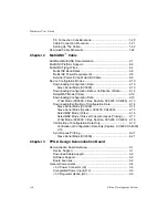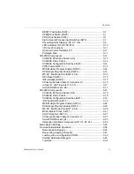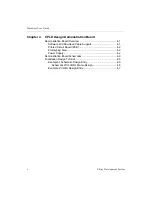
Contents
Hardware User Guide
ix
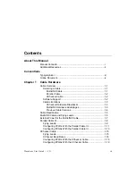
RESET Pushbutton (SW4)........................................................ 3-7
SPARE Pushbutton (SW5) ....................................................... 3-7
PROG Pushbutton (SW6) ......................................................... 3-7
Eight General-Purpose Input Switches (SW3).......................... 3-7
Seven-Segment Displays (U6, U7, U8) .................................... 3-9
LED Indicators (D1-D8, D9-D16) .............................................. 3-10
I/O Line Connections ................................................................ 3-11
Optional Crystal Oscillator (Y1)................................................. 3-11
Prototype Area .......................................................................... 3-11
XC4003E Components .................................................................. 3-12
XC4003E FPGA and Socket (U5)............................................. 3-13
XC4003E Probe Points ............................................................. 3-14
XC4003E Configuration Switches (SW2).................................. 3-14
PWR-Power (SW2–1) ............................................................... 3-14
MPE-Multiple Program Enable (SW2-2) ................................... 3-14
SPE-Single Program Enable (SW2-3) ...................................... 3-14
M0, M1, M2-Mode Pins (SW2-4,5,6) ........................................ 3-15
RST-Reset (SW2-7).................................................................. 3-15
INIT-Initialize (SW2-8)............................................................... 3-15
XChecker/Parallel Cable III Connector J2 ................................ 3-15
Jumper J7 and Tiepoints J10 (1-3) ........................................... 3-17
Serial PROM Socket (U2) ......................................................... 3-17
XC3020A Components .................................................................. 3-18
XC3020A FPGA and Socket (U4)............................................. 3-19
XC3020A Probe Points ............................................................. 3-19
XC3020A Configuration Switches (SW1).................................. 3-19
INP-Input Switch (SW1-1)......................................................... 3-19
MPE-Multiple Program Enable (SW1-2) ................................... 3-20
SPE-Single Program Enable (SW1-3) ...................................... 3-20
M0, M1, M2-Mode Pins (SW1-4,5,6) ........................................ 3-20
MCLK-Master Clock (SW1-7) ................................................... 3-21
DOUT-Data Out (SW1–8) ......................................................... 3-21
XChecker/Parallel Cable III Connector J1 ................................ 3-21
Serial PROM Socket (U1) ......................................................... 3-23
Relaxation Oscillator Components (R1 C5, R2 C6).................. 3-23
Mode Switch Settings..................................................................... 3-25
Demonstration Board Operation ................................................... 3-30
Demonstration Designs............................................................. 3-30
Design Downloading Checklist ................................................. 3-31
Loading with a Configuration PROM......................................... 3-32
Starting Hardware Debugger .................................................... 3-33
Tutorials .................................................................................... 3-34
Содержание MultiLINX DLC4
Страница 2: ...Hardware User Guide ...
Страница 10: ...Hardware User Guide vi Xilinx Development System ...
Страница 38: ...Hardware User Guide 1 24 Xilinx Development System ...
Страница 108: ...Hardware User Guide Glossary 4 Xilinx Development System ...

